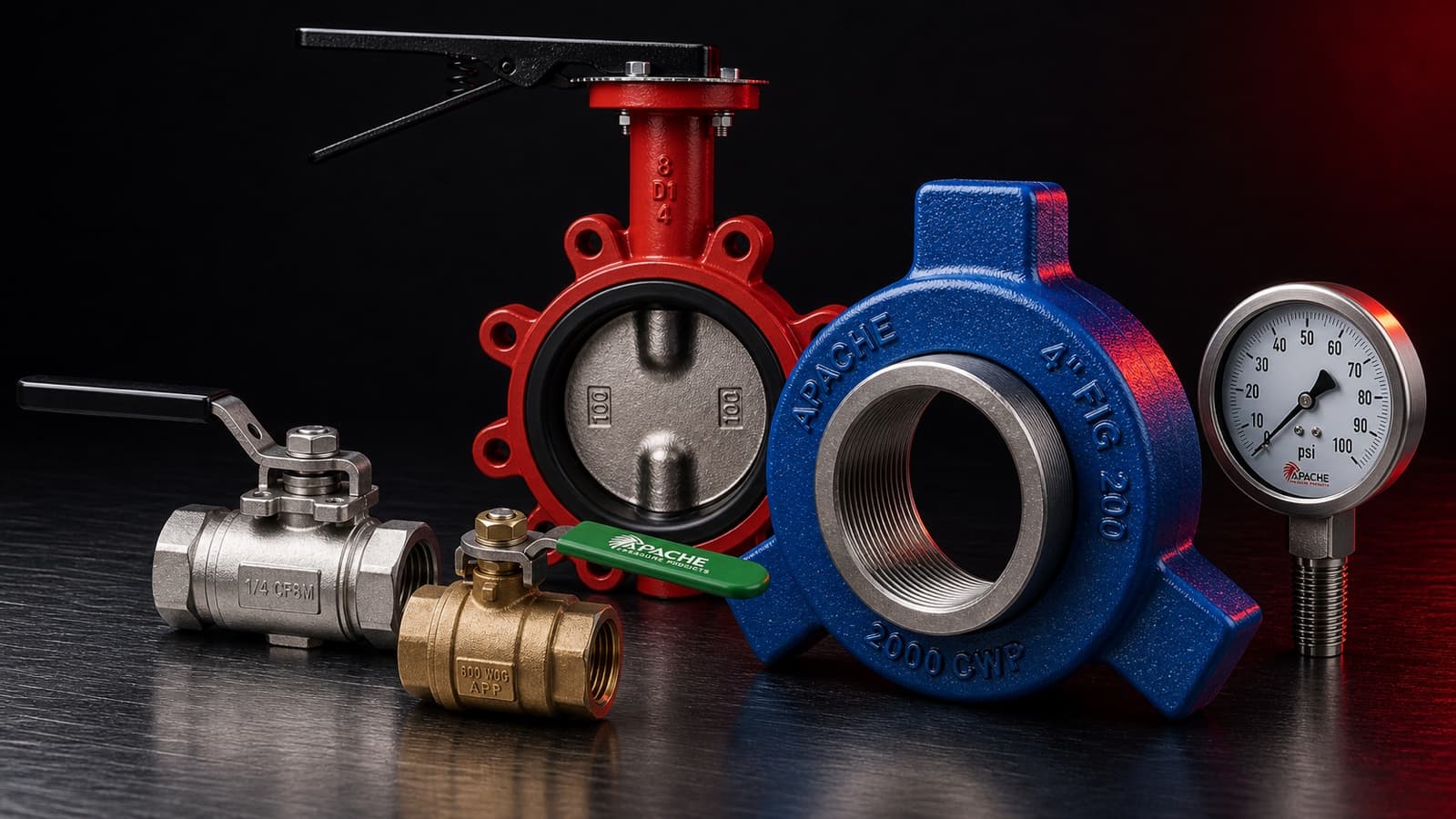
Apache Pressure Products

Product Catalog

Flow control,
stocked & shipped.

Six product lines covering the wellhead to the flowline — carbon steel to full stainless, NACE-compliant, and on the shelf in Houston and Odessa.

Featured Series

Workhorse ball valves

Three series, three duty levels — every one full port with a blow-out proof stem.

CFT2M SERIES — Two-Piece 2000 PSI Full Port Threaded Ball ValveCFT2M SERIES

Two-Piece 2000 PSI Full Port Threaded Ball Valve

Cast steel body with full stainless 316 internals. The balance point between cost and capability for industrial and commercial service.

  • Blow-out proof stem for safety
  • NACE MR0175 compliant
  • Locking handle minimizes unintended operation
Pressure rating
2000 PSI WOG (2.5”–3”: 1500 / 4”: 1000)
Body
Cast steel A216-WCB
Ball / Stem
AISI 316, floating ball
Seats
PTFE / RTFE
Sizes
1/4” – 4” NPT, full port
Threads
ANSI B1.20.1, BS21, DIN 259/2999
SWFT2M SERIES — Seal-Weld 2000 PSI Full Port Threaded Ball ValveSWFT2M SERIES

Seal-Weld 2000 PSI Full Port Threaded Ball Valve

Full 316 stainless construction with a seal-welded body for demanding service where leak paths are not an option.

  • Blow-out proof stem for safety
  • NACE MR0175 compliant
  • Locking handle minimizes unintended operation
Pressure rating
2000 PSI WOG (2.5”–4”: 1500)
Body
316 stainless, CF8M, seal-welded
Ball / Stem
AISI 316, floating ball
Seats
PTFE
Sizes
1/4” – 4” NPT, full port
Threads
ANSI B1.20.1, BS21, DIN 259/2999
BFT600 SERIES — Two-Piece 600 PSI Full Port Threaded Brass Ball ValveBFT600 SERIES

Two-Piece 600 PSI Full Port Threaded Brass Ball Valve

All-forged brass construction with PTFE seats and packing. Dependable shutoff in a compact body for general industrial service.

  • Full-port brass body for low restriction flow
  • Blow-out proof stem for safety
  • All forged construction for better durability
Pressure rating
600 WOG / 150 SWP
Body / Cap
Forged brass
Ball
Brass, chrome plated
Seats / Packing
PTFE
Sizes
1/4” – 4” NPT, full port
Threads
ANSI B1.20.1, BS21, DIN 259/2999

Full Line Card

Six lines deep

01

Valves

Ball, needle, check, gate, globe, and butterfly — threaded and flanged, carbon steel to full stainless.

Valves product line

Oilfield Ball Valves

  • CSBV SERIES
    Two-Piece Carbon Steel Oilfield Ball Valve

    Two-Piece Carbon Steel Oilfield Ball Valve

    The Apache CSBV Series is a two-piece carbon steel oilfield ball valve for demanding service. Carbon steel body construction, floating ball design, color-coded pressure ratings up to 5000 WOG, blow-out proof stem, locking plate, grease fitting, and NACE MR-0175 compliance.

    • Color coded up to 5000 WOG
    • Blow-out proof stem for safety
    • NACE MR-0175 compliant

    Dimensional Data

    CSBV SERIES dimension reference diagram
    Dimension reference — see table below for values
    SKUNPTColorWPBHG
    CSBV30RT-22” RPBrown30005.505.638.50
    CSBV30FT-11” FPBrown30004.003.066.25
    CSBV30FT-22” FPBrown30006.006.008.50
    CSBV30FT-33” FPBrown30008.756.7815.00
    CSBV30FT-44” FPBrown30009.377.8714.96
    CSBV50RT-22” RPRed50005.505.638.50

    Dimensions in inches. RP = reduced port · FP = full port · WP = working pressure (WOG). B = body length · H = installed height · G = handle length.

    Materials / Construction

    No.PartMaterial
    1BodyA216 WCB
    2BonnetA216 WCB
    3Ball304SS
    4SeatDelrin
    5Stem304SS
    6Stem WasherTeflon
    7Stem O’ringViton
    8Thrust BearingTeflon
    9Stop CollarA194 2H
    10Snap Ring6150
    11HandleA395
    12Body SealViton
    13Handle BoltA193 B7
    14Stop ScrewA193 B7

    Standards & Options

    Pressure Rating
    Color coded, up to 5000 WOG
    Body
    Carbon steel body
    Port
    Full port and reduced port models
    Valve Style
    Two-piece oilfield ball valve
    Ball
    Floating ball
    Stem
    Blow-out proof stem
    Handle
    Locking plate
    Feature
    Grease fitting
    Threads
    ANSI B1.20.1, BS21, DIN 259/2999
    Compliance
    NACE MR-0175 compliant

    Design may be subject to change without notice · Consult sales for specific requirements

    Download PDF
  • CSBV-B SERIES
    Bolted Body Carbon Steel Oilfield Ball Valve

    Bolted Body Carbon Steel Oilfield Ball Valve

    The Apache CSBV-B Series is a heavier-duty, bolted-body version of Apache's carbon steel oilfield ball valve. A flanged body connection adds reliability, with a standard top grease fitting, floating ball, blow-out proof stem, locking plate, and NACE MR-0175 compliance — color coded up to 5000 WOG.

    • Bolted body connection for more reliable service
    • Color coded up to 5000 WOG
    • Floating ball with blow-out proof stem

    Dimensional Data

    CSBV-B SERIES dimension reference diagram
    Dimension reference — see table below for values
    SKUNPTColorWPLHW
    CSBV30RB-22” RPBrown30005.504.848.50
    CSBV50RB-22” RPRed50005.504.848.50
    CSBV50FB-22” FPRed50005.756.1014.96
    CSBV50FB-33” FPRed50008.117.4031.50

    Dimensions in inches. RP = reduced port · FP = full port · WP = working pressure (WOG). L = body length · H = installed height · W = handle width.

    Materials / Construction

    No.PartMaterial
    1BodyA216 WCB / ASTM A105
    2CapA216 WCB / ASTM A105
    3Stem304SS
    4Ball304SS
    5Body SealViton
    6Stem BearingPTFE
    7SeatDelrin
    8StopSteel
    9Stem SealViton
    10Thrust BearingPTFE
    11HandleDuctile Iron
    12Stop PlateSteel
    13Stem BearingSpring Steel
    14Body BoltsASTM A193 B7M

    Standards & Options

    Pressure Rating
    Color coded, up to 5000 WOG
    Body
    Carbon steel body / A216 WCB or ASTM A105
    Valve Style
    Bolted body oilfield ball valve
    Ball
    Floating ball
    Stem
    Blow-out proof stem
    Feature
    Grease fitting
    Threads
    ANSI B1.20.1, BS21, DIN 259/2999
    Compliance
    NACE MR-0175 compliant

    Design may be subject to change without notice · Consult sales for specific requirements

    Download PDF
  • DIBV SERIES
    Two-Piece Ductile Iron Oilfield Ball Valve

    Two-Piece Ductile Iron Oilfield Ball Valve

    The Apache DIBV Series is a two-piece ductile iron oilfield ball valve for demanding service. Ductile iron body construction, floating ball design, color-coded pressure ratings up to 2000 WOG, blow-out proof stem, locking plate, grease fitting, and NACE MR-0175 compliance.

    • Color coded up to 2000 WOG
    • Blow-out proof stem for safety
    • NACE MR-0175 compliant

    Dimensional Data

    DIBV SERIES dimension reference diagram
    Dimension reference — see table below for values
    SKUNPTColorWPBHG
    DIBV15FT-11” FPBlue15004.003.066.25
    DIBV20FT-11” FPGreen20004.003.066.25
    DIBV10RT-22” RPMaroon10005.505.638.50
    DIBV15RT-22” RPBlue15005.505.638.50
    DIBV20RT-22” RPGreen20005.505.638.50
    DIBV20FT-22” FPGreen20006.006.008.50
    DIBV10RT-33” RPMaroon10006.005.888.50
    DIBV20RT-33” RPGreen20006.005.888.50
    DIBV20FT-33” FPGreen20008.756.7815.00
    DIBV10RT-44” RPMaroon10008.756.7815.00
    DIBV20RT-44” RPGreen20008.756.7815.00

    Dimensions in inches. RP = reduced port · FP = full port · WP = working pressure (WOG). B = body length · H = installed height · G = handle length. Color coded by pressure rating.

    Materials / Construction

    No.PartMaterial
    1BodyA395
    2BonnetA395
    3Ball304SS
    4SeatDelrin
    5Stem304SS
    6Stem WasherTeflon
    7Stem O’ringViton
    8Thrust BearingTeflon
    9Stop CollarA194 2H
    10Snap Ring6150
    11HandleA395
    12Body SealViton
    13Handle BoltA193 B7
    14Stop ScrewA193 B7

    Standards & Options

    Pressure Rating
    Color coded, up to 2000 WOG
    Body
    Ductile iron body
    Port
    Full port and reduced port models
    Valve Style
    Two-piece oilfield ball valve
    Ball
    Floating ball
    Stem
    Blow-out proof stem
    Handle
    Locking plate
    Feature
    Grease fitting
    Threads
    ANSI B1.20.1, BS21, DIN 259/2999
    Compliance
    NACE MR-0175 compliant

    Design may be subject to change without notice · Consult sales for specific requirements

    Download PDF

Threaded Ball Valves

  • CRT2M SERIES
    One-Piece 2000 PSI Reduced Port Threaded Ball Valve

    One-Piece 2000 PSI Reduced Port Threaded Ball Valve

    The Apache CRT2M Series is a one-piece 2000 PSI reduced-port threaded ball valve for industrial and commercial applications. Forged steel body construction, floating ball design, blow-out proof stem, RPTFE seat, and NACE MR-0175 compliance.

    • Forged steel body
    • Blow-out proof stem for safety
    • NACE MR-0175 compliant

    Dimensional Data

    CRT2M SERIES dimension reference diagram
    Dimension reference — see table below for values
    SKUNPTLDHW
    CRT2M0250R1/4”1.690.201.342.76
    CRT2M0375R3/8”1.850.281.462.76
    CRT2M0500R1/2”2.460.352.364.72
    CRT2M0750R3/4”2.760.492.524.72
    CRT2M1000R1”3.390.632.604.84
    CRT2M1250R1-1/4”3.700.793.075.71
    CRT2M1500R1-1/2”4.020.963.315.91
    CRT2M2000R2”4.531.263.585.91

    Dimensions in inches. Reduced-port threaded ball valve.

    Materials / Construction

    No.PartMaterial
    1BodyASTM A105
    2SeatRPTFE
    3BallAISI 304
    4Joint GasketPTFE
    5Thrust WasherPTFE
    6StemAISI 316
    7Stem PackingPTFE
    8Gland NutA194 Gr. 8
    9HandleAISI 304
    10WasherAISI 304
    11Handle SleevePVC

    Standards & Options

    Pressure Rating
    2000 PSI
    Body
    Forged steel body
    Port
    Reduced port
    Valve Style
    One-piece threaded ball valve
    Ball
    Floating ball
    Stem
    Blow-out proof stem
    Seats
    RPTFE seat
    Threads
    ANSI B1.20.1, BS21, DIN 259/2999
    Compliance
    NACE MR-0175 compliant

    Pressure / Temperature

    2000 PSI · RPTFE limit

    050010001500200025000100200300400500TEMPERATURE °FPRESSURE PSI

    Design may be subject to change without notice · Consult sales for specific requirements

    Download PDF
  • CFT2M SERIES
    Two-Piece 2000 PSI Full Port Threaded Ball Valve

    Two-Piece 2000 PSI Full Port Threaded Ball Valve

    The Apache CFT2M Series is a two-piece full-port threaded ball valve for industrial and commercial applications. Cast steel body with full stainless 316 internals, a locking handle, and NACE MR-0175 compliance — a strong balance of cost and capability.

    • Blow-out proof stem for safety
    • NACE MR0175 compliant
    • Locking handle minimizes unintended operation

    Dimensional Data

    CFT2M SERIES dimension reference diagram
    Dimension reference — see table below for values
    SKUNPTABCD
    CFT2M0250F1/4”0.462.351.973.94
    CFT2M0375F3/8”0.502.351.973.94
    CFT2M0500F1/2”0.512.511.973.94
    CFT2M0750F3/4”0.792.952.364.92
    CFT2M1000F1”0.983.552.766.30
    CFT2M1250F1-1/4”1.264.023.156.30
    CFT2M1500F1-1/2”1.504.563.547.48
    CFT2M2000F2”1.975.423.547.48
    CFT2M2500F2-1/2”2.566.224.808.66
    CFT2M3000F3”3.157.515.249.84
    CFT2M4000F4”3.948.946.3812.60

    Dimensions in inches. Sizes 2”+ are seal welded. 2.5”–3”: 1,500 PSI; 4”: 1,000 PSI.

    Materials / Construction

    No.PartMaterial
    1BodyA216-WCB
    2CapA216-WCB
    3BallAISI 316
    4SeatPTFE / RTFE
    5Joint GasketPTFE
    6StemAISI 316
    7Thrust WasherPTFE
    8Stem PackingPTFE
    9Gland NutASTM A2-70
    10Spring WasherAISI 304
    11Stem NutAISI 304
    12HandleAISI 304
    13Locking DeviceAISI 304
    14Handle SleevePVC

    Standards & Options

    Pressure Rating
    2000 PSI standard; 2.5”–3”: 1,500 PSI; 4”: 1,000 PSI
    Body
    Cast steel A216-WCB
    Port
    Full port
    Valve Style
    Two-piece threaded ball valve
    Ball
    Floating ball
    Stem
    Blow-out proof stem
    Handle
    Locking handle
    Threads
    ANSI B1.20.1, BS21, DIN 259/2999
    Compliance
    NACE MR-0175 compliant

    Pressure / Temperature

    2000 PSI WOG

    050010001500200025000100200300400TEMPERATURE °FPRESSURE PSI

    Design may be subject to change without notice · Consult sales for specific requirements

    Download PDF
  • CFT3M SERIES
    Two-Piece Class 1500 Full Port Threaded Ball Valve

    Two-Piece Class 1500 Full Port Threaded Ball Valve

    The Apache CFT3M Series is a two-piece Class 1500 full-port threaded ball valve for industrial and commercial applications. Cast steel body construction, floating ball design, fire safe API 607 compliance, ISO 5211 mounting pad, blow-out proof stem, locking handle, and NACE MR-0175 compliance.

    • Fire safe API 607 design
    • ISO 5211 mounting pad
    • NACE MR-0175 compliant

    Dimensional Data

    CFT3M SERIES dimension reference diagram
    Dimension reference — see table below for values
    SKUNPTABCD
    CFT3M0250F1/4”0.253.002.225.00
    CFT3M0500F1/2”0.504.002.225.00
    CFT3M0750F3/4”0.754.302.895.83
    CFT3M1000F1”1.004.803.508.19
    CFT3M1500F1-1/2”1.505.304.3410.16

    Dimensions in inches. Source part numbers shown as SKU.

    Materials / Construction

    No.PartMaterial
    1BodyWCB
    2CapWCB
    3BallCF8M
    4SeatDELRIN
    5Joint GasketGRAPHITE
    6StemSS316 or 17-4 (1-1/2”, 2”)
    7Thrust WasherDELRIN
    8Stem PackingGRAPHITE
    9Gland NutAISI 304
    10Spring WasherAISI 304
    11Stem NutAISI 304
    12HandleAISI 304
    13Locking DeviceAISI 304
    14Handle SleevePVC

    Standards & Options

    Pressure Rating
    ASME B16.34 Class 1500, 3705 WOG
    Body
    Cast steel body, floating ball
    Port
    Full port
    Valve Style
    Two-piece threaded ball valve
    Fire Safe
    API 607
    Stem
    Blow-out proof stem
    Mounting
    ISO 5211 mounting pad
    Handle
    Locking handle
    Threads
    ANSI B1.20.1, BS21, DIN 259/2999
    Compliance
    NACE MR-0175 compliant

    Pressure / Temperature

    Class 1500 · 3705 WOG

    08001600240032004000100200300400500TEMPERATURE °FPRESSURE PSI

    Design may be subject to change without notice · Consult sales for specific requirements

    Download PDF
  • CFT6M SERIES
    Two-Piece Class 2500 Full Port Threaded Ball Valve

    Two-Piece Class 2500 Full Port Threaded Ball Valve

    The Apache CFT6M Series is a two-piece Class 2500 threaded ball valve for industrial and commercial applications. Cast steel body, floating ball, fire-safe API 607 design, ISO 5211 mounting pad, blow-out proof stem, locking handle, and NACE MR-0175 compliance.

    • Class 2500 / 6000 WOG rating
    • Fire safe API 607 design
    • NACE MR-0175 compliant

    Dimensional Data

    CFT6M SERIES dimension reference diagram
    Dimension reference — see table below for values
    SKUNPTABCD
    CFT6M0250F1/4”0.253.002.225.00
    CFT6M0500F1/2”0.504.002.225.00
    CFT6M0750F3/4”0.754.302.895.83
    CFT6M1000F1”1.004.803.508.19
    CFT6M1500F1-1/2”1.505.304.3410.16
    CFT6M2000R2”1.506.304.3410.16

    Dimensions in inches. 2” available in standard port only.

    Materials / Construction

    No.PartMaterial
    1BodyWCB
    2CapWCB
    3BallCF8M
    4SeatPEEK
    5Joint GasketGraphite
    6StemSS316 or 17-4 (1-1/2”, 2”)
    7Thrust WasherPEEK
    8Stem PackingGraphite
    9Gland NutAISI 304
    10Spring WasherAISI 304
    11Stem NutAISI 304
    12HandleAISI 304
    13Locking DeviceAISI 304
    14Handle SleevePVC

    Standards & Options

    Pressure Rating
    ASME B16.34 Class 2500, 6000 WOG
    Body
    Cast steel body, floating ball
    Port
    Full port; 2” available in standard port only
    Valve Style
    Two-piece threaded ball valve
    Fire Safe
    API 607
    Stem
    Blow-out proof stem
    Mounting
    ISO 5211 mounting pad
    Handle
    Locking handle
    Threads
    ANSI B1.20.1, BS21, DIN 259/2999
    Compliance
    NACE MR-0175 compliant

    Pressure / Temperature

    Class 2500 / 6000 WOG

    012002400360048006000100200300400500TEMPERATURE °FPRESSURE PSI

    Design may be subject to change without notice · Consult sales for specific requirements

    Download PDF
  • SRT1M SERIES
    One-Piece 1000 PSI Reduced Port Threaded Ball Valve

    One-Piece 1000 PSI Reduced Port Threaded Ball Valve

    The Apache SRT1M Series is a one-piece 1000 PSI reduced-port threaded ball valve for industrial and commercial applications. 316 stainless body, floating ball, blow-out proof stem, locking handle, and NACE MR-0175 compliance.

    • 316 stainless body
    • Blow-out proof stem for safety
    • NACE MR-0175 compliant

    Dimensional Data

    SRT1M SERIES dimension reference diagram
    Dimension reference — see table below for values
    SKUNPTdLL₁H
    SRT1M0250R1/4”0.201.572.761.34
    SRT1M0375R3/8”0.281.772.761.42
    SRT1M0500R1/2”0.352.173.541.54
    SRT1M0750R3/4”0.472.363.541.69
    SRT1M1000R1”0.592.764.131.81
    SRT1M1250R1-1/4”0.793.154.722.09
    SRT1M1500R1-1/2”0.983.395.122.32
    SRT1M2000R2”1.264.025.512.56

    Dimensions in inches. Reduced-port threaded ball valve.

    Materials / Construction

    No.PartMaterial
    1BodyCF8M
    2BallCF8M
    3SeatPTFE
    4Joint GasketPTFE
    5NutAISI 304
    6StemCF8M
    7Stem WasherPTFE
    8PackingPTFE
    9Gland NutAISI 304
    10Stem NutAISI 304
    11Spring WasherAISI 304
    12HandleAISI 304
    13Handle SleevePVC

    Standards & Options

    Pressure Rating
    1000 PSI
    Body
    316 stainless body
    Port
    Reduced port
    Valve Style
    One-piece threaded ball valve
    Ball
    Floating ball
    Stem
    Blow-out proof stem
    Handle
    Locking handle
    Threads
    ANSI B1.20.1, BS21, DIN 259/2999
    Compliance
    NACE MR-0175 compliant

    Pressure / Temperature

    1000 PSI · PTFE limit

    025050075010000100200300400TEMPERATURE °FPRESSURE PSI

    Design may be subject to change without notice · Consult sales for specific requirements

    Download PDF
  • SWFT2M SERIES
    Seal-Weld 2000 PSI Full Port Threaded Ball Valve

    Seal-Weld 2000 PSI Full Port Threaded Ball Valve

    The Apache SWFT2M Series is a seal-weld full-port threaded ball valve for demanding service. Full 316 stainless construction, floating ball, blow-out proof stem, locking handle, and NACE MR-0175 compliance.

    • Blow-out proof stem for safety
    • NACE MR0175 compliant
    • Locking handle minimizes unintended operation

    Dimensional Data

    SWFT2M SERIES dimension reference diagram
    Dimension reference — see table below for values
    SKUNPTABCD
    SWFT2M0250F1/4”0.462.251.973.94
    SWFT2M0375F3/8”0.502.251.973.94
    SWFT2M0500F1/2”0.512.511.973.94
    SWFT2M0750F3/4”0.792.952.364.92
    SWFT2M1000F1”0.983.552.766.30
    SWFT2M1250F1-1/4”1.264.023.156.30
    SWFT2M1500F1-1/2”1.504.563.547.48
    SWFT2M2000F2”1.975.413.547.48
    SWFT2M2500F2-1/2”2.566.424.808.66
    SWFT2M3000F3”3.157.505.249.84
    SWFT2M4000F4”3.948.946.3812.60

    Dimensions in inches. 2.5”–4” rated 1,500 PSI.

    Materials / Construction

    No.PartMaterial
    1BodyCF8M
    2CapCF8M
    3BallAISI 316
    4SeatPTFE
    5Joint GasketPTFE
    6StemAISI 316
    7Thrust WasherPTFE
    8Stem PackingPTFE
    9Gland NutASTM A2-70
    10Spring WasherAISI 304
    11Stem NutAISI 304
    12HandleAISI 304
    13Locking DeviceAISI 304
    14Handle SleevePVC

    Standards & Options

    Pressure Rating
    2000 PSI standard; 2.5”–4”: 1,500 PSI
    Body
    316 stainless, CF8M
    Port
    Full port
    Valve Style
    Seal-weld threaded ball valve
    Ball
    Floating ball
    Stem
    Blow-out proof stem
    Handle
    Locking handle
    Threads
    ANSI B1.20.1, BS21, DIN 259/2999
    Compliance
    NACE MR-0175 compliant

    Pressure / Temperature

    2000 PSI WOG

    050010001500200025000100200300400TEMPERATURE °FPRESSURE PSI

    Design may be subject to change without notice · Consult sales for specific requirements

    Download PDF
  • SFT3M SERIES
    Seal-Weld Class 1500 Full Port Threaded Ball Valve

    Seal-Weld Class 1500 Full Port Threaded Ball Valve

    The Apache SFT3M Series is a seal-weld Class 1500 threaded ball valve for industrial and commercial applications. SS316 body, floating ball, fire-safe API 607 design, ISO 5211 mounting pad, blow-out proof stem, locking handle, and NACE MR-0175 compliance.

    • Fire safe API 607 design
    • ISO 5211 mounting pad
    • NACE MR-0175 compliant

    Dimensional Data

    SFT3M SERIES dimension reference diagram
    Dimension reference — see table below for values
    SKUNPTABCD
    SFT3M0250F1/4”0.253.002.225.00
    SFT3M0500F1/2”0.504.002.225.00
    SFT3M0750F3/4”0.754.302.895.83
    SFT3M1000F1”1.004.803.508.19
    SFT3M1500F1-1/2”1.505.304.3410.16
    SFT3M2000R2”1.506.304.3410.16

    Dimensions in inches. 2” available in standard port only.

    Materials / Construction

    No.PartMaterial
    1BodyCF8M
    2CapCF8M
    3BallCF8M
    4SeatDelrin
    5Joint GasketGraphite
    6StemSS316 or 17-4 (1-1/2”, 2”)
    7Thrust WasherDelrin
    8Stem PackingGraphite
    9Gland NutAISI 304
    10Spring WasherAISI 304
    11Stem NutAISI 304
    12HandleAISI 304
    13Locking DeviceAISI 304
    14Handle SleevePVC

    Standards & Options

    Pressure Rating
    ASME B16.34 Class 1500, 3600 WOG
    Body
    SS316 body, floating ball
    Port
    Full port; 2” available in standard port only
    Valve Style
    Seal-weld threaded ball valve
    Fire Safe
    API 607
    Stem
    Blow-out proof stem
    Mounting
    ISO 5211 mounting pad
    Handle
    Locking handle
    Threads
    ANSI B1.20.1, BS21, DIN 259/2999
    Compliance
    NACE MR-0175 compliant

    Pressure / Temperature

    Class 1500 / 3600 WOG

    08001600240032004000100200300400500TEMPERATURE °FPRESSURE PSI

    Design may be subject to change without notice · Consult sales for specific requirements

    Download PDF
  • SFT6M SERIES
    Seal-Weld Class 2500 Full Port Threaded Ball Valve

    Seal-Weld Class 2500 Full Port Threaded Ball Valve

    The Apache SFT6M Series is a seal-weld Class 2500 threaded ball valve for industrial and commercial applications. SS316 body, floating ball, fire-safe API 607 design, ISO 5211 mounting pad, blow-out proof stem, locking handle, and NACE MR-0175 compliance.

    • Class 2500 / 6000 WOG rating
    • Fire safe API 607 design
    • NACE MR-0175 compliant

    Dimensional Data

    SFT6M SERIES dimension reference diagram
    Dimension reference — see table below for values
    SKUNPTABCD
    SFT6M0250F1/4”0.253.002.225.00
    SFT6M0500F1/2”0.504.002.225.00
    SFT6M0750F3/4”0.754.302.895.83
    SFT6M1000F1”1.004.803.508.19
    SFT6M1500F1-1/2”1.505.304.3410.16
    SFT6M2000R2”1.506.304.3410.16

    Dimensions in inches. 2” available in standard port only.

    Materials / Construction

    No.PartMaterial
    1BodyCF8M
    2CapCF8M
    3BallCF8M
    4SeatPEEK
    5Joint GasketGraphite
    6StemSS316 or 17-4 (1-1/2”, 2”)
    7Thrust WasherPEEK
    8Stem PackingGraphite
    9Gland NutAISI 304
    10Spring WasherAISI 304
    11Stem NutAISI 304
    12HandleAISI 304
    13Locking DeviceAISI 304
    14Handle SleevePVC

    Standards & Options

    Pressure Rating
    ASME B16.34 Class 2500, 6000 WOG
    Body
    SS316 body, floating ball
    Port
    Full port; 2” available in standard port only
    Valve Style
    Seal-weld threaded ball valve
    Fire Safe
    API 607
    Stem
    Blow-out proof stem
    Mounting
    ISO 5211 mounting pad
    Handle
    Locking handle
    Threads
    ANSI B1.20.1, BS21, DIN 259/2999
    Compliance
    NACE MR-0175 compliant

    Pressure / Temperature

    Class 2500 / 6000 WOG

    012002400360048006000100200300400500TEMPERATURE °FPRESSURE PSI

    Design may be subject to change without notice · Consult sales for specific requirements

    Download PDF
  • BFT600 SERIES
    Two-Piece 600 PSI Full Port Threaded Ball Valve

    Two-Piece 600 PSI Full Port Threaded Ball Valve

    The Apache BFT600 Series is a two-piece full-port threaded brass ball valve for general industrial and commercial service. Forged brass construction, PTFE seats and packing, and a blow-out proof stem provide dependable shutoff performance in a compact valve body.

    • Full-port brass body for low restriction flow
    • Blow-out proof stem for safety
    • All forged construction for better durability

    Dimensional Data

    BFT600 SERIES dimension reference diagram
    Dimension reference — see table below for values
    Part #NPTLWH
    BFT6C0250F1/4”1.793.071.46
    BFT6C0375F3/8”1.793.071.46
    BFT6C0500F1/2”2.093.261.46
    BFT6C0750F3/4”2.393.282.06
    BFT6C1000F1”2.724.722.31
    BFT6C1250F1-1/4”3.285.802.99
    BFT6C1500F1-1/2”3.305.953.15
    BFT6C2000F2”4.657.873.54
    BFT6C2000H2” HD4.727.873.54
    BFT6C2500F2-1/2”5.518.314.82
    BFT6C3000F3”6.388.315.24
    BFT6C4000F4”7.4410.236.14

    Dimensions in inches. L = end-to-end length · W = handle width · H = installed height

    Materials / Construction

    No.PartMaterial
    1CapForged Brass
    2SeatPTFE
    3BallBrass, Chrome Plated
    4BodyForged Brass
    5StemForged Brass
    6WasherPTFE
    7PackingPTFE
    8PackingPTFE
    9Gland NutBrass
    10HandleSteel, Zinc Plated
    11RetainerSteel, Zinc Plated
    12Stem NutSteel, Zinc Plated

    Standards & Options

    Pressure Rating
    600 WOG, 150 SWP
    Body
    Forged brass body and cap
    Port
    Full port
    Valve Style
    Two-piece threaded ball valve
    Seats / Packing
    PTFE seats, washer, and packing
    Threads
    ANSI B1.20.1, BS21, DIN 259/2999
    Application
    Not intended for potable water

    Pressure / Temperature

    600 WOG / 150 SWP

    02004006000100200300400TEMPERATURE °FPRESSURE PSI

    Design may be subject to change without notice · Consult sales for specific requirements

    Download PDF

Needle Valves

  • NV6 SERIES
    6000 PSI Needle Valve

    6000 PSI Needle Valve

    The Apache NV6 Series is a compact 6000 PSI needle valve for controlled isolation and throttling in oilfield service. Available in carbon steel or stainless construction, it supports MNPT × FNPT and FNPT × FNPT threaded connections with Delrin or PEEK seats for dependable shutoff across a range of pressures and service applications.

    • 6000 PSI CWP
    • Delrin or PEEK seats
    • Carbon or stainless body

    Dimensional Data

    NV6 SERIES dimension reference diagram
    Dimension reference — see table below for values
    SKUMaterialInletOutletLDH
    CNV025M025F06Carbon Steel1/4” MNPT1/4” FNPT3.272.372.65
    CNV025F025F06Carbon Steel1/4” FNPT1/4” FNPT2.962.372.65
    CNV050M050F06Carbon Steel1/2” MNPT1/2” FNPT3.272.372.65
    CNV050F050F06Carbon Steel1/2” FNPT1/2” FNPT2.962.372.65
    CNV075M075F06Carbon Steel3/4” MNPT3/4” FNPT3.272.372.65
    CNV075F075F06Carbon Steel3/4” FNPT3/4” FNPT2.962.372.65
    CNV100M100F06Carbon Steel1” MNPT1” FNPT3.732.372.65
    CNV100F100F06Carbon Steel1” FNPT1” FNPT3.422.372.65
    SNV025M025F06Stainless1/4” MNPT1/4” FNPT3.272.372.65
    SNV025F025F06Stainless1/4” FNPT1/4” FNPT2.962.372.65
    SNV050M050F06Stainless1/2” MNPT1/2” FNPT3.272.372.65
    SNV050F050F06Stainless1/2” FNPT1/2” FNPT2.962.372.65
    SNV075M075F06Stainless3/4” MNPT3/4” FNPT3.272.372.65
    SNV075F075F06Stainless3/4” FNPT3/4” FNPT2.962.372.65
    SNV100M100F06Stainless1” MNPT1” FNPT3.732.372.65
    SNV100F100F06Stainless1” FNPT1” FNPT3.422.372.65

    Dimensions in inches. CNV = carbon steel · SNV = stainless. L = end-to-end length · D = handle diameter · H = installed height.

    Materials / Construction

    No.PartMaterial
    1Bonnet Pin304SS
    2Stem316SS
    3Tee HandleAISI 1045 +Zn (C) / A182 F6a (SS)
    4Handle Nut410SS
    5BonnetAISI 1045 +Zn (C) / 316SS (SS)
    6O-ringViton
    7SeatDelrin / PEEK
    8O-ringViton
    9BodyAISI 1045 +Zn (C) / 316SS (SS)
    10NutNBR

    Standards & Options

    Pressure Rating
    6000 PSI CWP
    Body
    Carbon steel or stainless body
    Valve Style
    Gate-style needle valve
    Connections
    MNPT × FNPT, FNPT × FNPT
    Seats
    Delrin or PEEK
    Compliance
    NACE MR-0175 compliant

    Pressure / Temperature

    6000 PSI CWP

    012002400360048006000100200300400500PEEKDelrinTEMPERATURE °FPRESSURE PSI

    Design may be subject to change without notice · Consult sales for specific requirements

    Download PDF
  • NV10 SERIES
    10000 PSI Needle Valve

    10000 PSI Needle Valve

    The Apache NV10 Series is a higher-pressure, metal-seated needle valve for precise flow control and positive isolation in severe oilfield service. Globe-style construction supports 10000 PSI CWP applications in carbon steel or stainless, with threaded MNPT × FNPT and FNPT × FNPT connections.

    • 10000 PSI CWP
    • Metal seats
    • Carbon or stainless body

    Dimensional Data

    NV10 SERIES dimension reference diagram
    Dimension reference — see table below for values
    SKUMaterialInletOutletLDH
    CNV025M025F10Carbon Steel1/4” MNPT1/4” FNPT3.272.372.65
    CNV025F025F10Carbon Steel1/4” FNPT1/4” FNPT2.962.372.65
    CNV050M050F10Carbon Steel1/2” MNPT1/2” FNPT3.272.372.65
    CNV050F050F10Carbon Steel1/2” FNPT1/2” FNPT2.962.372.65
    CNV075M075F10Carbon Steel3/4” MNPT3/4” FNPT3.272.372.65
    CNV075F075F10Carbon Steel3/4” FNPT3/4” FNPT2.962.372.65
    CNV100M100F10Carbon Steel1” MNPT1” FNPT3.732.372.65
    CNV100F100F10Carbon Steel1” FNPT1” FNPT3.422.372.65
    SNV025M025F10Stainless1/4” MNPT1/4” FNPT3.272.372.65
    SNV025F025F10Stainless1/4” FNPT1/4” FNPT2.962.372.65
    SNV050M050F10Stainless1/2” MNPT1/2” FNPT3.272.372.65
    SNV050F050F10Stainless1/2” FNPT1/2” FNPT2.962.372.65
    SNV075M075F10Stainless3/4” MNPT3/4” FNPT3.272.372.65
    SNV075F075F10Stainless3/4” FNPT3/4” FNPT2.962.372.65
    SNV100M100F10Stainless1” MNPT1” FNPT3.732.372.65
    SNV100F100F10Stainless1” FNPT1” FNPT3.422.372.65

    Dimensions in inches. CNV = carbon steel · SNV = stainless. L = end-to-end length · D = handle diameter · H = installed height.

    Materials / Construction

    No.PartMaterial
    1Bonnet Pin304SS
    2Stem316SS
    3Tee HandleAISI 1045 +Zn (C) / A182 F6a (SS)
    4Handle Nut410SS
    5BonnetAISI 1045 +Zn (C) / 316SS (SS)
    6O-ringViton
    8O-ringViton
    9BodyAISI 1045 +Zn (C) / 316SS (SS)
    10NutNBR

    Standards & Options

    Pressure Rating
    10000 PSI CWP
    Body
    Carbon steel or stainless body
    Valve Style
    Globe-style needle valve
    Connections
    MNPT × FNPT, FNPT × FNPT
    Seats
    Metal seats
    Compliance
    NACE MR-0175 compliant

    Pressure / Temperature

    10000 PSI CWP · Metal seat

    0200040006000800010000100200300400500TEMPERATURE °FPRESSURE PSI

    Design may be subject to change without notice · Consult sales for specific requirements

    Download PDF
  • MP6 SERIES
    6000 PSI Multiport Needle Valve

    6000 PSI Multiport Needle Valve

    The Apache MP6 Series is a 6000 PSI multiport needle valve for oilfield applications requiring controlled isolation with auxiliary port access. Its compact threaded body supports MNPT × FNPT service, with Delrin seating and optional plug-and-bleed configurations for field flexibility.

    • 2 × 1/2” NPT ports
    • Optional plug & bleed set
    • Delrin seats

    Dimensional Data

    MP6 SERIES dimension reference diagram
    Dimension reference — see table below for values
    SKUMaterialInletOutletLDH
    CMP05M05F06Carbon Steel1/2” MNPT1/2” FNPT4.472.372.65
    SMP05M05F06Stainless1/2” MNPT1/2” FNPT4.472.372.65

    Dimensions in inches. CMP = carbon steel · SMP = stainless. L = end-to-end length · D = handle diameter · H = installed height.

    Materials / Construction

    No.PartMaterial
    1Bonnet Pin304SS
    2Stem316SS
    3Tee HandleAISI 1045 +Zn (C) / A182 F6a (SS)
    4Handle Nut410SS
    5BonnetAISI 1045 +Zn (C) / 316SS (SS)
    6O-ringViton
    7SeatDelrin / PEEK
    8O-ringViton
    9BodyAISI 1045 +Zn (C) / 316SS (SS)
    10NutNBR

    Standards & Options

    Pressure Rating
    6000 PSI CWP
    Body
    Carbon steel or stainless body
    Valve Style
    Gate-style multiport needle valve
    Connections
    MNPT × FNPT
    Ports
    2 × 1/2” NPT ports
    Option
    Optional plug & bleed set

    Pressure / Temperature

    6000 PSI CWP · Delrin seat

    012002400360048006000100200300400500TEMPERATURE °FPRESSURE PSI

    Design may be subject to change without notice · Consult sales for specific requirements

    Download PDF
  • MP10 SERIES
    10000 PSI Multiport Needle Valve

    10000 PSI Multiport Needle Valve

    The Apache MP10 Series is a high-pressure, metal-seated multiport needle valve for demanding isolation, instrument, and bleed applications. Globe-style construction supports 10000 PSI CWP service while retaining auxiliary 1/2-inch port access for plug-and-bleed configurations.

    • 2 × 1/2” NPT ports
    • Optional plug & bleed set
    • Metal seats

    Dimensional Data

    MP10 SERIES dimension reference diagram
    Dimension reference — see table below for values
    SKUMaterialInletOutletLDH
    CMP05M05F10Carbon Steel1/2” MNPT1/2” FNPT4.472.372.65
    SMP05M05F10Stainless1/2” MNPT1/2” FNPT4.472.372.65

    Dimensions in inches. CMP = carbon steel · SMP = stainless. L = end-to-end length · D = handle diameter · H = installed height. Bleed and plug are sold separately.

    Materials / Construction

    No.PartMaterial
    1Tee HandleAISI 1045 +Zn (C) / A182 F6a (SS)
    2Handle Nut410SS
    3Dust CapNBR (red)
    4Stem316SS
    5Bonnet Pin304SS
    6BonnetAISI 1045 +Zn (C) / 316SS (SS)
    7O-ringViton
    8O-ringViton
    9SeatMetal
    10BodyAISI 1045 +Zn (C) / 316SS (SS)

    Standards & Options

    Pressure Rating
    10000 PSI CWP
    Body
    Carbon steel or stainless body
    Valve Style
    Globe-style multiport needle valve
    Connections
    MNPT × FNPT
    Ports
    2 × 1/2” NPT ports
    Option
    Optional plug & bleed set

    Design may be subject to change without notice · Consult sales for specific requirements

    Download PDF
  • MNV6 SERIES
    6000 PSI Mini Needle Valve

    6000 PSI Mini Needle Valve

    The Apache MNV6 Series is a compact 6000 PSI mini needle valve for tight installations and instrument runs. Carbon steel or stainless body in a compact mini-valve package, available with tee or round handles and multiple 1/4-inch threaded connection styles for flexible field installation.

    • Compact mini body
    • Tee or round handle
    • Metal seats

    Dimensional Data

    MNV6 SERIES dimension reference diagram
    Dimension reference — see table below for values
    SKUMaterialHandleInletOutletLDH
    CMT025M025F06A105Tee1/4” MNPT1/4” FNPT1.891.262.55
    SMT025M025F06SS316Tee1/4” MNPT1/4” FNPT1.891.262.55
    CMR025M025F06A105Round1/4” MNPT1/4” FNPT1.890.982.55
    SMR025M025F06SS316Round1/4” MNPT1/4” FNPT1.890.982.55
    CMT025F025F06A105Tee1/4” FNPT1/4” FNPT1.891.262.55
    SMT025F025F06SS316Tee1/4” FNPT1/4” FNPT1.891.262.55
    CMR025F025F06A105Round1/4” FNPT1/4” FNPT1.890.982.55
    SMR025F025F06SS316Round1/4” FNPT1/4” FNPT1.890.982.55

    Dimensions in inches. CM = carbon steel · SM = stainless · T = tee handle · R = round handle. L = end-to-end length · D = handle diameter/width · H = installed height.

    Materials / Construction

    No.PartMaterial
    1HandleAISI 1045 (C) / 316SS (SS)
    2Handle Nut410SS
    3BonnetAISI 1045 (C) / 316SS (SS)
    4Stem316SS
    5O-ringViton
    6O-ringViton
    7BodyAISI 1045 (C) / 316SS (SS)

    Standards & Options

    Pressure Rating
    6000 PSI CWP
    Body
    Carbon steel or stainless body
    Valve Style
    Mini globe-style needle valve
    Connections
    MNPT × FNPT, FNPT × FNPT, MNPT × MNPT
    Ports
    2 × 1/4” NPT ports
    Compliance
    NACE MR-0175 compliant

    Pressure / Temperature

    6000 PSI CWP

    012002400360048006000100200300400500TEMPERATURE °FPRESSURE PSI

    Design may be subject to change without notice · Consult sales for specific requirements

    Download PDF

Butterfly Valves

  • DWB200 SERIES
    Wafer Butterfly Valve

    Wafer Butterfly Valve

    The Apache DWB200 Series is a 200 PSI wafer-style butterfly valve with a ductile iron body, square stem, and 10-position locking handle. Designed to ISO 5752 face-to-face with an ISO 5211 mounting pad and ANSI 150 flange fit, with multiple seat and disc selections for broad media compatibility.

    • 200 PSI ductile iron body
    • 10-position locking handle
    • ANSI 150 flange · ISO 5211 mounting pad

    Dimensional Data

    DWB200 SERIES dimension reference diagram
    Dimension reference — see table below for values
    SizeABCØDLSTorque (ft·lb)
    2”2.993.941.104.751.650.62514
    3”3.664.921.106.001.770.62529
    4”4.296.021.107.502.050.62548
    6”5.356.691.109.502.200.625109
    8”6.549.451.5011.752.360.875177
    10”7.8311.221.5014.252.600.875280
    12”9.3711.811.5017.003.031.125397
    16”12.1315.7521.253.391.125

    Dimensions in inches. ØD = flange OD · L = face-to-face (ISO 5752) · S = stem square. Full ISO 5211 mounting-pad and flange-bolt dimensions on the official spec sheet. The 16” is gear-operated (handwheel); “—” marks values not shown on its drawing.

    Materials / Construction

    No.PartMaterial
    1BodyDuctile Iron
    2O-RingBuna-N / EPDM / FKM
    3Lower StemSS410
    4DiscDI / CF8M / Al Bronze
    5SeatEPDM / Buna-N / PTFE / FKM
    6BushingPTFE
    7Top StemSS410

    Standards & Options

    Pressure Rating
    200 PSI
    Body
    Ductile iron, wafer style
    Stem
    Square stem, 10-position handle
    Seats
    Buna, EPDM, Teflon, FKM
    Disc Options
    Nickel-plated DI, aluminum bronze, SS316
    Face-to-Face
    ISO 5752
    Mounting
    ISO 5211 pad
    Flange
    ANSI 150

    Design may be subject to change without notice · Consult sales for specific requirements

    Download PDF
  • DLB200 SERIES
    Lug Butterfly Valve

    Lug Butterfly Valve

    The Apache DLB200 Series is a 200 PSI lug-style butterfly valve with a ductile iron body, square stem, and 10-position locking handle. Tapped lugs allow dead-end and downstream-flange service, with an ISO 5211 mounting pad, ANSI 150 flange fit, and multiple disc selections.

    • 200 PSI ductile iron lug body
    • Tapped lugs for dead-end service
    • ANSI 150 flange · ISO 5211 mounting pad

    Dimensional Data

    DLB200 SERIES dimension reference diagram
    Dimension reference — see table below for values
    SizeABCØDLSLug TapTorque (ft·lb)
    2”2.993.941.104.751.650.6254 · 5/8-11 UNC14
    3”3.664.921.106.001.770.6254 · 5/8-11 UNC29
    4”4.296.021.107.502.050.6258 · 5/8-11 UNC48
    6”5.356.691.109.502.200.6258 · 3/4-10 UNC109
    8”6.549.451.5011.752.360.8758 · 3/4-10 UNC177
    10”7.8311.221.5014.252.600.87512 · 7/8-9 UNC280
    12”9.3711.811.5017.003.031.12512 · 7/8-9 UNC397
    16”12.1315.7521.253.391.12516 · 1”-8 UNC

    Dimensions in inches. ØD = flange OD · L = face-to-face (ISO 5752) · S = stem square · Lug Tap = qty · thread per flange. Full ISO 5211 mounting-pad dimensions on the official spec sheet. The 16” is gear-operated (handwheel); “—” marks values not shown on its drawing.

    Materials / Construction

    No.PartMaterial
    1BodyDuctile Iron
    2O-RingBuna-N / EPDM / FKM
    3Lower StemSS410
    4DiscDI / CF8M / Al Bronze
    5SeatEPDM / Buna-N / PTFE / FKM
    6BushingPTFE
    7Top StemSS410

    Standards & Options

    Pressure Rating
    200 PSI
    Body
    Ductile iron, lug style
    Stem
    Square stem, 10-position handle
    Seats
    Buna or Viton
    Disc Options
    Nickel-plated DI, aluminum bronze, SS316
    Face-to-Face
    ISO 5752
    Mounting
    ISO 5211 pad
    Flange
    ANSI 150

    Design may be subject to change without notice · Consult sales for specific requirements

    Download PDF

Check, Gate & Globe Valves

  • DICV SERIES
    Ductile Iron Swing Check Valve

    Ductile Iron Swing Check Valve

    The Apache DICV Series is a ductile iron swing check valve for dependable reverse-flow prevention in general oilfield and industrial service. The A395 ductile iron body carries a 304 stainless disc and is offered from 300 to 2000 WOG, with threaded end connections.

    • 300 – 2000 WOG ratings
    • A395 ductile iron body and bonnet
    • 304SS disc, swing-check design

    Dimensional Data

    DICV SERIES dimension reference diagram
    Dimension reference — see table below for values
    Part #NPTWP (PSI)ABC
    DICV2M11”20003.034.721.00
    DICV3C22”3003.946.302.01
    DICV6C22”6003.946.302.01
    DICV1M22”10003.946.302.01
    DICV2M22”20003.946.302.01
    DICV3C33”3005.208.253.07
    DICV2M33”20005.208.253.07
    DICV2M44”20007.6810.004.00

    Dimensions in inches. B = end-to-end length; A and C per the spec-sheet drawing. Sizes 2” and 3” share a body across multiple WOG ratings.

    Materials / Construction

    No.PartMaterial
    1BodyA395 Ductile Iron
    2Disc304SS
    3O-RingViton
    4GasketBuna-N
    5BonnetA395 Ductile Iron

    Standards & Options

    Pressure Rating
    300 / 600 / 1000 / 2000 WOG
    Body
    A395 ductile iron body and bonnet
    Valve Style
    Bolted-bonnet swing check
    Threads
    ANSI B1.20.1, BS21, DN 259/2999
    Compliance
    NACE MR-0175 compliant

    Design may be subject to change without notice · Consult sales for specific requirements

    Download PDF
  • CSCV SERIES
    Carbon Steel Swing Check Valve

    Carbon Steel Swing Check Valve

    The Apache CSCV Series is a cast carbon steel swing check valve for higher-pressure reverse-flow prevention. The A216 WCB body carries a 304 stainless disc and is rated to 5000 WOG, with threaded end connections in 1” through 3” sizes.

    • 5000 WOG
    • A216 WCB cast steel body
    • 304SS disc, swing-check design

    Dimensional Data

    CSCV SERIES dimension reference diagram
    Dimension reference — see table below for values
    Part #NPTWP (PSI)ABC
    CSCV5M11”50003.034.721.00
    CSCV5M22”50003.946.302.01
    CSCV5M33”50005.208.253.07

    Dimensions in inches. B = end-to-end length; A and C per the spec-sheet drawing.

    Materials / Construction

    No.PartMaterial
    1BodyA216 WCB
    2Disc304SS
    3O-RingViton
    4GasketBuna-N
    5BonnetA216 WCB

    Standards & Options

    Pressure Rating
    5000 WOG
    Body
    A216 WCB cast carbon steel
    Valve Style
    Bolted-bonnet swing check
    Threads
    ANSI B1.20.1, BS21, DN 259/2999
    Compliance
    NACE MR-0175 compliant

    Design may be subject to change without notice · Consult sales for specific requirements

    Download PDF
  • FSC SERIES
    Forged Steel Class 800 Swing Check Valve

    Forged Steel Class 800 Swing Check Valve

    The Apache FSC Series is a Class 800 forged steel swing check valve for compact, high-integrity reverse-flow prevention. The A105 forged body with CR13 stainless trim is designed to API 602, fire-safe per API 607, and NACE MR-0175 compliant, with bolted-bonnet construction and threaded end connections.

    • Class 800 forged steel body
    • API 602 · fire-safe API 607
    • CR13 stainless trim · NACE MR-0175

    Dimensional Data

    FSC SERIES dimension reference diagram
    Dimension reference — see table below for values
    Part #NPTNPSL
    FSC2M05001/2”1/2”3.11
    FSC2M07503/4”3/4”3.62
    FSC2M10001”1”4.37
    FSC2M20002”2”6.77

    Dimensions in inches. L = end-to-end length.

    Materials / Construction

    No.PartMaterial
    1BodyA105
    2DiscA182 F6a
    3SeatA182 F6a
    4GasketSS + Flexible Graphite
    5BonnetA105
    6BoltASTM A193 B7M
    7PinPEEK
    8HingeGraphite
    9NutAISI 304

    Standards & Options

    Pressure Rating
    Class 800
    Body
    A105 forged steel, CR13 stainless trim
    Valve Style
    Bolted-bonnet swing check
    Design
    API 602
    Fire Safe
    API 607
    Threads
    ANSI B1.20.1, BS21, DN 259/2999
    Compliance
    NACE MR-0175 compliant

    Pressure / Temperature

    Class 800

    0500100015002000250002004006008001000TEMPERATURE °FPRESSURE PSI

    Design may be subject to change without notice · Consult sales for specific requirements

    Download PDF

Flanged Ball Valves

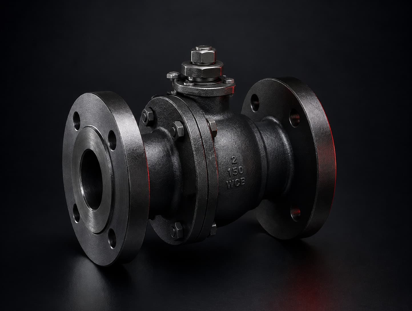
  • FL-150A SERIES
    Class 150 Full-Port Flanged Ball Valve

    Class 150 Full-Port Flanged Ball Valve

    The Apache FL-150A Series is a Class 150 full-port flanged floating ball valve designed and manufactured to API 6D. The cast steel body features a blow-out proof stem, locking handle, and ISO 5211 mounting pad, and is fire-safe (API 607), anti-static, and NACE MR-0175 compliant.

    • Class 150 full port · API 6D
    • Floating ball · blow-out proof stem
    • Fire-safe API 607 · anti-static · ISO 5211 pad

    Dimensional Data

    FL-150A SERIES dimension reference diagram
    Dimension reference — see table below for values
    NPSLdDD1D2n-ØdfbF1F2P
    2”7.001.965.914.753.630.16–0.750.060.63F07F050.551
    3”7.992.997.486.005.000.16–0.750.060.75F10F070.669
    4”9.003.949.067.506.190.31–0.750.060.94F10F070.866
    6”15.515.9111.029.508.500.31–0.870.061.13F12F101.063

    Dimensions in inches. L = face-to-face · d = bore · D = flange OD · n-Ød = bolt count–hole dia · F1/F2 = ISO 5211 pad. Full Class 150 flange data on the spec sheet.

    Materials / Construction

    No.PartMaterial
    1BodyA216 WCB
    2CapA216 WCB
    3Body GasketSS + Graphite
    4SeatRPTFE
    5BallSS316
    6StemSS316
    7Thrust WasherPTFE
    8Stem O-RingViton
    9PackingGraphite
    10Packing GlandSS
    11StopCarbon Steel
    12HandleCarbon Steel

    Standards & Options

    Pressure Rating
    ANSI Class 150
    Body
    Cast steel, full port
    Ball
    Floating ball
    Stem
    Blow-out proof, locking handle
    Design / Mfg
    API 6D
    Fire Safe
    API 607, anti-static
    Mounting
    ISO 5211 pad
    Compliance
    NACE MR-0175 compliant

    Design may be subject to change without notice · Consult sales for specific requirements

    Download PDF
  • FL-300A SERIES
    Class 300 Flanged Floating Ball Valve

    Class 300 Flanged Floating Ball Valve

    The Apache FL-300A Series is a Class 300 flanged floating ball valve in cast steel, designed in accordance with ISO 17292 and tested to API 6D. Offered lever-operated in 2”–4” and gear-operated in 6”–8”, with stainless ball and stem and NACE MR-0175 compliance for severe oilfield service.

    • ANSI Class 300 · API 6D tested
    • Floating ball · ISO 17292 design
    • Lever (2”–4”) or gear (6”–8”) operated

    Dimensional Data

    FL-300A SERIES dimension reference diagram
    Dimension reference — see table below for values
    NPSdGCDtn-ØhLHW
    2”2.013.625.006.500.878–19.18.505.4315.75
    3”2.995.006.628.251.128–22.211.146.8917.72
    4”4.026.197.8810.001.258–22.212.017.9519.69
    6”5.988.5010.6212.501.4412–22.215.879.4515.75
    8”7.9910.6213.0015.001.6212–25.419.7611.3415.75

    Dimensions in inches. d = bore · C/D = flange · n-Øh = bolt count–hole dia · L = face-to-face. 2”–4” lever operated; 6”–8” gear operated.

    Materials / Construction

    No.PartMaterial
    1BodyASTM A216 WCB
    2SeatRPTFE
    3BallASTM A182 F316
    4StemASTM A182 F51
    5Antistatic SpringInconel X-750
    6Thrust WasherSS + Copper + RPTFE
    7O-RingViton
    8PackingGraphite
    9GlandStainless Steel
    10Body StudASTM A193 B7M
    11Body NutASTM A194 2HM
    12AdapterASTM A216 WCB

    Standards & Options

    Pressure Rating
    ANSI Class 300
    Body
    Cast steel
    Ball
    Floating ball
    Design
    ISO 17292
    Testing
    API 6D
    Operator
    Lever (2”–4”) / gear (6”–8”)
    Compliance
    NACE MR-0175 compliant

    Design may be subject to change without notice · Consult sales for specific requirements

    Download PDF
  • FL-600A SERIES
    Class 600 Full-Port Flanged Ball Valve

    Class 600 Full-Port Flanged Ball Valve

    The Apache FL-600A Series is a Class 600 full-port flanged ball valve designed and manufactured to API 6D. Cast steel, carbon steel, or stainless construction with a blow-out proof stem and lockable lever handle, it is fire-safe (API 607), anti-static, API 641 low-emission, and fully NACE MR-0175 compliant.

    • Class 600 full port · API 6D
    • Fire-safe API 607 · anti-static
    • API 641 low emission · NACE MR-0175

    Dimensional Data

    FL-600A SERIES dimension reference diagram
    Dimension reference — see table below for values
    SizeLdDD1D2n-ØfbN·mPart #
    2”29250165127928–Ø196.425.570F1SF314FL-2R
    3”35676210168.31278–Ø226.432280F1SF314FL-3R
    4”432100275215.91578–Ø25.56.438.5340F1SF314FL-4R

    Dimensions in mm. L = face-to-face · d = bore · D = flange OD · n-Ø = bolt count–hole dia · N·m = seating torque. Face-to-face ASME B16.10 · flanges ASME B16.5.

    Materials / Construction

    No.PartMaterial
    1BodyA216 WCB / A352 LCC / A351 CF8M
    2CapA216 WCB / A352 LCC / A351 CF8M
    3BallA182 F316
    4SeatDevlon
    5StemA276 316
    6PackingGraphite
    7Thrust WasherPTFE
    8Packing GlandCS / SS
    9Lever TeeCS / SS
    10GasketSS + Graphite
    11BoltA193 B7M / A320 L7M / A193 B8M
    12NutA194 2HM / A194 GR.7M / A194 8M

    Standards & Options

    Pressure Rating
    ANSI Class 600, full port
    Body
    Cast / carbon / stainless steel
    Stem
    Blow-out proof, lockable lever
    Design / Mfg
    API 6D
    Fire Safe
    API 607, anti-static
    Emissions
    API 641 low emission
    Testing
    API 598
    Compliance
    NACE MR-0175 full compliance

    Design may be subject to change without notice · Consult sales for specific requirements

    Download PDF
  • VR-150A SERIES
    Class 150 Trunnion-Mounted Flanged Ball Valve

    Class 150 Trunnion-Mounted Flanged Ball Valve

    The Apache VR-150A Series is an API 6D, ANSI Class 150 trunnion-mounted flanged ball valve with a forged ASTM A105 body. It carries an electroless-nickel-plated (ENP) ball, 4140+ENP stem, and RPTFE seats with PTFE+SS bearings and a 17-7PH spring, and is gear-operated in 8”, 10”, and 12” sizes. Fire-safe to API 607, anti-static, and NACE MR-0175 compliant.

    • API 6D · ANSI Class 150 · trunnion mounted
    • Forged A105 body · ENP ball · 4140 stem
    • Fire-safe API 607 · NACE MR-0175 · gear operated

    Dimensional Data

    VR-150A SERIES dimension reference diagram
    Dimension reference — see table below for values
    NPSDNdLDD1D2n-ØbTorque
    8”2007.9118.0013.5011.7510.638 × Ø0.911.02540
    10”2509.9221.0016.0014.2512.7512 × Ø1.001.20830
    12”30011.9324.0019.0017.0015.0012 × Ø1.001.251400

    Dimensions in inches; DN in mm. d = bore · L = face-to-face · D = flange OD · D1 = bolt circle · D2 = raised-face OD · n-Ø = bolt count × hole dia · b = flange thickness · Torque = operating torque (N·m). Flanges per ASME B16.5.

    Materials / Construction

    No.PartMaterial
    1BodyASTM A105 (forged)
    2BonnetASTM A105
    3BallA105 + ENP
    4Stem4140 + ENP
    5SeatRPTFE
    6Seat RingA105 + ENP
    7BearingsPTFE + SS
    8Spring17-7PH
    9Anti-Static DeviceSS316
    10O-RingsViton
    11Sealing GasketsGraphite + SS
    12Studs / BoltsASTM A193 B7
    13NutsASTM A194 2H
    14Yoke / Stuff Box / CoverASTM A105
    15Vent / Injection / DrainCS + Zn
    16OperatorGear assembly

    Standards & Options

    Design / Manufacture
    API 6D
    Pressure Rating
    ANSI Class 150
    Flange
    ASME B16.5
    Pressure / Temp Rank
    ASME B16.34
    Fire Safe
    API 607, anti-static
    Test
    Shell 3.0 MPa · Seat 2.2 MPa · Air 0.4–0.7 MPa
    Service / Temp
    W.O.G · −29 to 120 °C
    Operation
    Gear operated
    Compliance
    NACE MR-0175
    Sizes
    8”, 10”, 12”

    Design may be subject to change without notice · Consult sales for specific requirements

    Download PDF
  • VR-600A SERIES
    Class 600 Trunnion-Mounted Flanged Ball Valve

    Class 600 Trunnion-Mounted Flanged Ball Valve

    The Apache VR-600A Series is a Class 600 trunnion-mounted flanged ball valve of three-piece (side-entry) construction for high-pressure pipeline service. A216 WCB left, center, and right bodies carry an electroless-nickel-plated (ENP) ball, stem, and metal seat rings, with integral drain and vent valves and lifting lugs.

    • ANSI Class 600 · trunnion mounted
    • 3-piece side-entry · A216 WCB body
    • ENP ball & metal seats · gear operated

    Dimensional Data

    VR-600A SERIES dimension reference diagram
    Dimension reference — see table below for values
    NPSDNdLDD1D2bfn-Ø
    6”1505.9122.0014.0011.508.501.880.2812 × Ø1.12

    Dimensions in inches; DN in mm. d = bore · L = face-to-face · D = flange OD · D1 = bolt circle · D2 = raised-face OD · b = flange thickness · f = raised-face height · n-Ø = bolt count × hole dia. Flanges per ANSI Class 600 (ASME B16.5). Additional sizes on request.

    Materials / Construction

    No.PartMaterial
    1Left / Right BodyA216 WCB
    2Center BodyA216 WCB
    3BallA105 + ENP
    4StemA105 + ENP
    5Seat RingsA105 + ENP
    6Upper CoverA105 + ENP
    7Lower CoverNylon
    8O-Rings / Washers304 + Graphite / Viton
    9BoltsA276 410
    10ScrewsA276 420 / Inconel X-750
    11Nuts / SpringsA193 B7M
    12Radial BearingA276 316 / CS-PTFE
    13Drain & Vent ValvesCS-PTFE / Viton
    14Lifting LugsCS + Zn

    Standards & Options

    Pressure Rating
    ANSI Class 600
    Design
    Trunnion-mounted, 3-piece side-entry flanged ball valve
    Body
    A216 WCB cast steel
    Ball / Stem
    A105 + ENP
    Seat Rings
    A105 + ENP (metal seat)
    Features
    Integral drain & vent valves, lifting lugs
    End Connections
    ANSI Class 600 flanged (raised face)
    Sizes
    6”

    Design may be subject to change without notice · Consult sales for specific requirements

    Download PDF

Flanged Check Valves

  • CV-150 SERIES
    Class 150 Flanged Swing Check Valve

    Class 150 Flanged Swing Check Valve

    The Apache CV-150 Series is a Class 150 flanged swing check valve in ASTM A216 WCB cast steel. A bolted bonnet, CF8M stainless-faced disc and hinge, and Viton seat deliver reliable non-return service for pipeline and process lines in 2” through 8” sizes.

    • ANSI Class 150 · swing check
    • A216 WCB body · CF8M disc & hinge
    • Bolted bonnet · Viton seat · 2”–8”

    Dimensional Data

    CV-150 SERIES dimension reference diagram
    Dimension reference — see table below for values
    NPSLdHDD1D2n-ØfT(Min)Wt (lb)
    2”7.991.975.555.914.753.634 × Ø0.750.080.6427
    3”9.492.996.897.486.005.004 × Ø0.750.080.7750
    4”11.504.027.729.067.506.198 × Ø0.750.080.9682
    6”14.025.989.9211.029.508.508 × Ø0.870.081.02133
    8”19.497.9111.3613.5011.7510.638 × Ø0.870.081.14237

    Dimensions in inches; weights in lb. L = face-to-face · d = bore · H = overall height · D = flange OD · D1 = bolt circle · D2 = raised-face OD · n-Ø = bolt count × hole dia · f = raised-face height · T(Min) = minimum wall thickness. Flanges per ASME B16.5 Class 150.

    Materials / Construction

    No.PartMaterial
    1BodyASTM A216 WCB
    2SeatViton
    3DiscASTM A216-WCB + CF8M
    4HingeCF8M
    5Hinge PinASTM A276 420
    6GasketFLEX Graphite / 316
    7BonnetASTM A216 WCB
    8Bonnet Bolt NutASTM A194 Gr. 2H
    9Bonnet BoltASTM A193 Gr. B7

    Standards & Options

    Pressure Rating
    ANSI Class 150
    Design
    Flanged swing check valve
    Body / Bonnet
    ASTM A216 WCB (bolted bonnet)
    Disc
    ASTM A216-WCB + CF8M
    Seat
    Viton
    End Connections
    ANSI Class 150 flanged (raised face)
    Sizes
    2”, 3”, 4”, 6”, 8”

    Design may be subject to change without notice · Consult sales for specific requirements

    Download PDF
  • CV-600 SERIES
    Class 600 Flanged Swing Check Valve

    Class 600 Flanged Swing Check Valve

    The Apache CV-600 Series is a Class 600 flanged swing check valve in ASTM A216 WCB cast steel with an ASTM A351 CF8M stainless disc, A105/Viton seat, and bolted bonnet. Built for high-pressure pipeline and process non-return service in 2”, 3”, and 4” sizes.

    • ANSI Class 600 · swing check
    • A216 WCB body · A351 CF8M disc
    • Bolted bonnet · 2”–4”

    Dimensional Data

    CV-600 SERIES dimension reference diagram
    Dimension reference — see table below for values
    NPSLdHDD1D2n-ØfT(Min)Wt (lb)
    2”11.501.976.366.505.003.628 × Ø0.750.281.2847
    3”14.022.998.078.276.635.008 × Ø0.870.281.5489
    4”17.014.029.5110.838.506.208 × Ø1.020.281.79170

    Dimensions in inches; weights in lb. L = face-to-face · d = bore · H = overall height · D = flange OD · D1 = bolt circle · D2 = raised-face OD · n-Ø = bolt count × hole dia · f = raised-face height · T(Min) = minimum wall thickness. Flanges per ASME B16.5 Class 600.

    Materials / Construction

    No.PartMaterial
    1BodyASTM A216 WCB
    2SeatASTM A105 / Viton
    3DiscASTM A351 CF8M
    4HingeASTM A216 WCB
    5Hinge PinASTM A276 420
    6GasketFLEX Graphite / 304
    7BonnetASTM A216 WCB
    8Bonnet Bolt NutASTM A194 Gr. 2H
    9Bonnet BoltASTM A193 Gr. B7

    Standards & Options

    Pressure Rating
    ANSI Class 600
    Design
    Flanged swing check valve
    Body / Bonnet
    ASTM A216 WCB (bolted bonnet)
    Disc
    ASTM A351 CF8M
    Seat
    ASTM A105 / Viton
    End Connections
    ANSI Class 600 flanged (raised face)
    Sizes
    2”, 3”, 4”

    Design may be subject to change without notice · Consult sales for specific requirements

    Download PDF
02

Flowline

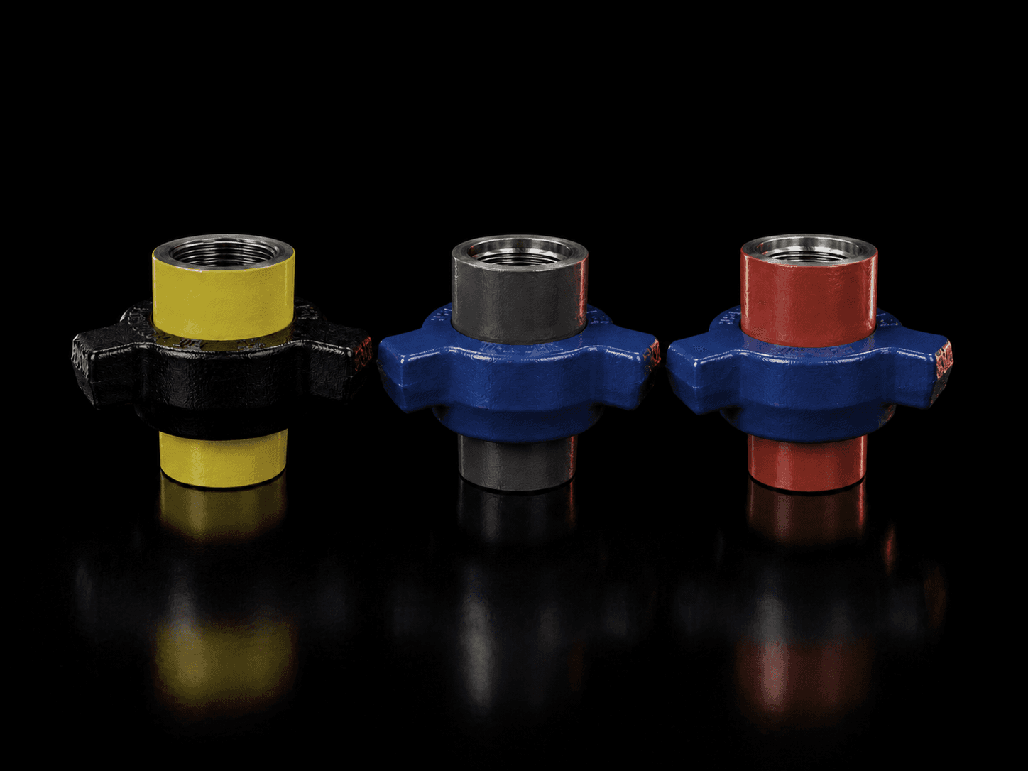
Hammer unions built for high-pressure flowline and frac service.

Flowline product line

Hammer Unions

  • FIG 100
    FIG 100 Hammer Union

    FIG 100 Hammer Union

    The Apache FIG 100 is an economical 1000 PSI hammer union for low-pressure water, oil, and gas (WOG) service. Metal-to-metal sealing and NPT threaded subs make it a dependable, quick make-and-break connection for general transfer and flowline work in sizes 2” through 8”.

    • 1000 PSI NSCWP
    • Metal-to-metal seal
    • Sizes 2”–8” · NPT threaded

    Dimensional Data

    FIG 100 dimension reference diagram
    Dimension reference — see table below for values
    Part #SizeABWeight (lb)
    A100T-2.02”2.943.665.60
    A100T-3.03”4.074.9214.00
    A100T-4.04”4.554.9223.00
    A100T-6.06”6.577.4848.00
    A100T-8.08”8.508.7259.00

    Dimensions (A, B) in inches; weights in lb. Male and female subs available in threaded and buttweld ends.

    Materials / Construction

    No.PartMaterial
    1Male SubA105 (2”) · CS (3–4”) · DI (6–8”)
    2Female SubA105 (2”) · CS (3–4”) · DI (6–8”)
    3NutCS (2–4”) · DI (6–8”)
    4SealMetal-to-metal

    Standards & Options

    Pressure Rating
    1000 PSI NSCWP
    Test Pressure
    1500 PSI
    Seal
    Metal-to-metal
    End Connections
    NPT threaded
    Sizes
    2”, 3”, 4”, 6”, 8”
    Service
    Standard (non-sour)

    Design may be subject to change without notice · Consult sales for specific requirements

    Download PDF
  • FIG 200 / 206
    FIG 200 / 206 Hammer Union

    FIG 200 / 206 Hammer Union

    The Apache FIG 200 / 206 is a general-purpose 2000 PSI hammer union for water, oil, and gas service. The FIG 200 seals metal-to-metal while the FIG 206 adds a Buna-N O-ring for positive low-pressure sealing, both with NPT threaded subs across 1” through 8”.

    • 2000 PSI NSCWP
    • Metal-to-metal (200) or Buna O-ring (206)
    • Sizes 1”–8” · NPT threaded

    Dimensional Data

    FIG 200 / 206 dimension reference diagram
    Dimension reference — see table below for values
    Part #SizeABWeight (lb)
    A200T/A206T-1.01”1.972.891.75
    A200T-1.51-1/2”2.382.852.37
    A200T/A206T-2.02”2.953.665.75
    A200T-2.52-1/2”3.744.2110.00
    A200T/A206T-3.03”3.965.0415.25
    A200T/A206T-4.04”4.554.9220.00
    A200T-6.06”6.577.4848.00
    A200T-8.08”8.508.7259.00

    Dimensions (A, B) in inches; weights in lb. FIG 206 (Buna O-ring) offered in 1”–4”.

    Materials / Construction

    No.PartMaterial
    1Male SubA105 · CS · DI (size dependent)
    2Female SubA105 · CS · DI (size dependent)
    3NutCS · DI (size dependent)
    4SealMetal-to-metal (200) / Buna-N O-ring (206)

    Standards & Options

    Pressure Rating
    2000 PSI NSCWP
    Test Pressure
    3000 PSI
    Seal
    Metal-to-metal (FIG 200) / Buna O-ring (FIG 206)
    End Connections
    NPT threaded
    Sizes
    1” – 8”
    Service
    Standard (non-sour)

    Design may be subject to change without notice · Consult sales for specific requirements

    Download PDF
  • FIG 300
    FIG 300 Hammer Union

    FIG 300 Hammer Union

    The Apache FIG 300 is a 2000 PSI flat-face hammer union with a Buna-N O-ring seal and straight break-out for fast, low-torque connection. Offered in 1” and 2” NPT, it suits instrument, manifold, and light flowline service.

    • 2000 PSI NSCWP
    • Flat-face Buna O-ring seal
    • Straight break-out · 1”–2”

    Dimensional Data

    FIG 300 dimension reference diagram
    Dimension reference — see table below for values
    Part #SizeABWeight (lb)
    A300T-1.01”1.942.691.75
    A300T-2.02”2.893.885.25

    Dimensions (A, B) in inches; weights in lb. Flat-face design with straight break-out.

    Materials / Construction

    No.PartMaterial
    1Male SubA105
    2Female SubA105
    3NutCarbon Steel
    4SealBuna-N O-ring (flat face)

    Standards & Options

    Pressure Rating
    2000 PSI NSCWP
    Test Pressure
    3000 PSI
    Seal
    Buna-N O-ring, flat face
    End Connections
    NPT threaded, straight break-out
    Sizes
    1”, 2”
    Service
    Standard (non-sour)

    Design may be subject to change without notice · Consult sales for specific requirements

    Download PDF
  • FIG 400
    FIG 400 Hammer Union

    FIG 400 Hammer Union

    The Apache FIG 400 is a 4000 PSI forged-steel hammer union with metal-to-metal sealing for medium-pressure WOG and flowline service. NPT threaded subs in 2”, 3”, and 4” provide a rugged, field-serviceable connection.

    • 4000 PSI NSCWP
    • Forged steel · metal-to-metal
    • Sizes 2”–4” · NPT threaded

    Dimensional Data

    FIG 400 dimension reference diagram
    Dimension reference — see table below for values
    Part #SizeABWeight (lb)
    A400T-2.02”3.645.2412.00
    A400T-3.03”4.196.2519.25
    A400T-4.04”5.008.1332.00

    Dimensions (A, B) in inches; weights in lb.

    Materials / Construction

    No.PartMaterial
    1Male SubA105 (2–3”) · 1020 (4”)
    2Female SubA105 (2–3”) · 1020 (4”)
    3NutCS (2–3”) · 1020 (4”)
    4SealMetal-to-metal

    Standards & Options

    Pressure Rating
    4000 PSI NSCWP
    Test Pressure
    6000 PSI
    Seal
    Metal-to-metal
    End Connections
    NPT threaded
    Sizes
    2”, 3”, 4”
    Service
    Standard (non-sour)

    Design may be subject to change without notice · Consult sales for specific requirements

    Download PDF
  • FIG 602
    FIG 602 Hammer Union

    FIG 602 Hammer Union

    The Apache FIG 602 is a 6000 PSI alloy-steel hammer union for higher-pressure circulating, cementing, and flowline service. A lip-type seal ring reduces turbulence, and subs are available in NPT threaded and buttweld ends; the 2” size is offered in an API 7HU1-compliant design.

    • 6000 PSI NSCWP
    • Alloy steel · lip-type seal ring
    • Threaded & buttweld · 1”–4”

    Dimensional Data

    FIG 602 dimension reference diagram
    Dimension reference — see table below for values
    Part #SizeConnection
    A602T-1.01”NPT threaded
    A602T-2.02”NPT threaded (API 7HU1)
    A602B160-2.02”XXH buttweld
    A602T-3.03”NPT threaded
    A602T-4.04”NPT threaded
    A602B160-4.04”XXH buttweld

    Connection options shown; A/B/weight dimensions per current cut sheet.

    Materials / Construction

    No.PartMaterial
    1Male Sub4130
    2Female Sub4130
    3Nut4130 (most sizes) · 4140 (larger)
    4SealLip-type seal ring

    Standards & Options

    Pressure Rating
    6000 PSI NSCWP
    Test Pressure
    9000 PSI
    Seal
    Lip-type seal ring (reduced turbulence)
    End Connections
    NPT threaded & buttweld
    Sizes
    1” – 4” (2” available API 7HU1)
    Service
    Standard (non-sour)

    Design may be subject to change without notice · Consult sales for specific requirements

    Download PDF
  • FIG 1502
    FIG 1502 Hammer Union

    FIG 1502 Hammer Union

    The Apache FIG 1502 is a 15,000 PSI alloy-steel hammer union for high-pressure well-service, fracturing, and cementing applications. A lip-type seal ring reduces turbulence, with 4130/4140 subs and nuts available in NPT threaded and XXH buttweld ends in 2” through 4”.

    • 15,000 PSI NSCWP
    • Alloy steel · lip-type seal ring
    • Threaded & XXH buttweld · 2”–4”

    Dimensional Data

    FIG 1502 dimension reference diagram
    Dimension reference — see table below for values
    Part #SizeABWeight (lb)
    A1502T-2.02” THD3.887.0018.50
    A1502B160-2.02” XXH BW3.886.7519.50
    A1502T-3.03” THD4.505.5025.00
    A1502B160-3.03” XXH BW4.505.5028.00
    A1502T-4.04” THD5.639.5061.00
    A1502B160-4.04” XXH BW5.639.5077.25

    Dimensions (A, B) in inches; weights in lb. THD = NPT threaded · XXH BW = extra-heavy buttweld.

    Materials / Construction

    No.PartMaterial
    1Male Sub4130
    2Female Sub4130
    3Nut4130 (2–3”) · 4140 (4”)
    4SealLip-type seal ring

    Standards & Options

    Pressure Rating
    15,000 PSI NSCWP
    Test Pressure
    22,500 PSI
    Seal
    Lip-type seal ring (reduced turbulence)
    End Connections
    NPT threaded & XXH buttweld
    Sizes
    2”, 3”, 4”
    Service
    Standard (non-sour)

    Design may be subject to change without notice · Consult sales for specific requirements

    Download PDF
03

Wellhead

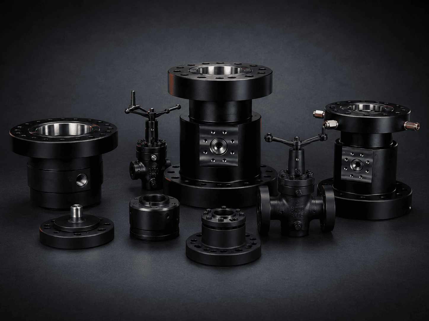
API 6A gate valves, heads, spools, flanges, hangers, seals, and gaskets — the full stack from surface casing up.

Wellhead product line

Gate Valves

  • E-SERIES
    E-Series Expanding Gate Valve

    E-Series Expanding Gate Valve

    The Apache E-Series is an API 6A expanding (wedge) gate valve for oil & gas wellheads, production trees, and other critical applications. The wedge gate forms a mechanical seal that does not rely on line pressure, delivering positive 5,000 psi shut-off in 2-1/16” through 7-1/16” bores, with flanged ends or threaded line-pipe / EUE tubing connections.

    • API 6A · 5,000 psi
    • Expanding wedge gate · mechanical seal
    • Flanged or threaded LP / EUE · 2-1/16”–7-1/16”

    Dimensional Data

    E-SERIES dimension reference diagram
    Dimension reference — see table below for values
    EndSizePressureBoreBCDETurnsWt (lb)
    Flanged2-1/16”5,0002.069.625.319.61313126
    Flanged2-9/16”5,0002.5610.256.120.61315-1/2142
    Flanged3-1/8”5,0003.1211.387.622.81620236
    Flanged4-1/16”5,0004.0613.009.425.91624-1/2454
    2” LP2-1/16”5,0002.0614.625.319.61313176
    2-3/8” EUE2-1/16”5,0002.0614.625.319.61313176
    2-7/8” EUE2-9/16”5,0002.5616.626.120.61315-1/2224
    3” LP3-1/8”5,0003.1216.627.622.81620334
    3-1/2” EUE3-1/8”5,0003.1216.627.622.81620334
    4” LP4-1/16”5,0004.0621.629.425.91624-1/2614
    4-1/2” EUE4-1/16”5,0004.0621.629.425.91624-1/2614

    Pressure in psi; dimensions in inches; weights in lb. B = end-to-end length · Turns = handwheel turns to open. Threaded ends: LP = line pipe, EUE = external-upset tubing. Larger bores to 7-1/16” available — consult factory.

    Standards & Options

    Specification
    API 6A
    Pressure Rating
    5,000 psi
    Bore Sizes
    2-1/16” – 7-1/16”
    Gate
    Expanding wedge gate (mechanical seal)
    End Connections
    Flanged or threaded (LP / EUE)
    Trim
    Material / temperature classes per API 6A
    Applications
    Wellheads, production trees, critical service

    Design may be subject to change without notice · Consult sales for specific requirements

  • S-SERIES
    S-Series Slab Gate Valve

    S-Series Slab Gate Valve

    The Apache S-Series is an API 6A forged-body, bi-directional slab gate valve for wellheads, production trees, fracturing, and other critical service. Offered from 2,000 to 15,000 psi in 1-13/16” through 7-1/16” bores with flanged ends and a full range of API ring grooves and trim levels.

    • API 6A · 2,000–15,000 psi
    • Forged body · bi-directional slab gate
    • Flanged · 1-13/16”–7-1/16”

    Dimensional Data

    S-SERIES dimension reference diagram
    Dimension reference — see table below for values
    SizePressureBoreBCDEAPI RingWt (lb)
    2-1/16”5,0002.0614.625.115.513.5R-24216
    2-9/16”5,0002.5616.625.916.513.5R-27289
    3-1/8”5,0003.1218.626.717.417R-35419
    4-1/16”5,0004.0621.628.319.117R-39688
    5-1/8”5,0005.1228.621124.418.75R-441387
    7-1/16”5,0007.0632.0015.327.625R-462187
    1-13/16”10,0001.8118.255.614.817BX-151243
    2-1/16”10,0002.0620.506.115.517BX-152329
    2-9/16”10,0002.5622.256.816.517BX-153410
    3-1/16”10,0003.0624.387.917.418.75BX-154518
    4-1/16”10,0004.0626.389.819.118.75BX-1551118
    5-1/8”10,0005.1229.0012.724.425BX-1691528
    1-13/16”15,0001.8118.005.914.817BX-151260
    2-1/16”15,0002.0619.006.515.517BX-152315
    2-9/16”15,0002.5621.007.716.518.75BX-153576
    3-1/16”15,0003.0623.56917.418.75BX-154602

    Pressure in psi; dimensions in inches; weights in lb. R-series ring grooves are used at 5,000 psi, BX-series at 10,000 and 15,000 psi. Trim and PSL levels per API 6A — consult trim chart.

    Standards & Options

    Specification
    API 6A
    Pressure Rating
    2,000 – 15,000 psi
    Bore Sizes
    1-13/16” – 7-1/16”
    Gate
    Bi-directional forged slab gate
    End Connections
    Flanged (R / BX ring joint)
    Trim / PSL
    Per API 6A (consult trim chart)
    Applications
    Wellheads, production trees, fracturing

    Design may be subject to change without notice · Consult sales for specific requirements

Wellhead Components

  • CASING HEADS
    C-22 Casing Head

    C-22 Casing Head

    Apache casing heads feature a C-22 straight-bore bowl with 45° load shoulders that protect the sealing area from drilling-tool damage and eliminate bowl-protector wedging under pressure. Built to API 6A with line-pipe and side-studded outlets, rated 2,000 / 3,000 / 5,000 psi.

    • API 6A · 2,000 / 3,000 / 5,000 psi
    • C-22 straight-bore bowl · 45° load shoulders
    • Line-pipe & side-studded outlets

    Dimensional Data

    CASING HEADS dimension reference diagram
    Dimension reference — see table below for values
    Casing SizeTop FlangeABC
    8-5/8”11”17.25–17.508.0010.88
    9-5/8”11”17.25–17.509.0010.88
    10-3/4”11”17.25–17.5010.0010.88
    11-3/4”13-5/8”17.5012.5613.50
    13-3/8”13-5/8”17.5012.5613.50

    Dimensions in inches. A shown across the 2,000–5,000 psi ratings; weights run 300–780 lb by size and rating. C-22 profile with 45° load shoulders.

    Standards & Options

    Specification
    API 6A
    Working Pressure
    2,000 / 3,000 / 5,000 psi
    Bowl Profile
    C-22 straight bore, 45° load shoulders
    Outlets
    Line-pipe and side-studded
    Top Flanges
    11” and 13-5/8”
    Accepts
    C-22 casing hangers / secondary seals

    Design may be subject to change without notice · Consult sales for specific requirements

  • TUBING SPOOLS
    Tubing Spool

    Tubing Spool

    Apache tubing spools use a TCM bowl design with 45° landing shoulders. Built to API 6A with line-pipe and side-studded outlets, they accept TCM-style tubing hangers and support PE, HPE, and PP bottom-seal preparations.

    • API 6A construction
    • TCM bowl · 45° landing shoulders
    • Accepts TCM-style tubing hangers

    Dimensional Data

    TUBING SPOOLS dimension reference diagram
    Dimension reference — see table below for values
    Bottom FlangeBottom WPTop FlangeTop WPABCWt (lb)
    11”3,0007-1/16”3,00023.126.767.00600
    11”3,0007-1/16”5,00026.256.767.00670
    11”3,0009”3,00026.258.258.75750
    11”3,0009”5,00026.258.258.75800
    11”5,0007-1/16”5,00026.256.767.00880
    11”5,0007-1/16”10,00031.256.767.00856
    11”5,0009”10,00031.258.258.751249
    11”10,0007-1/16”10,00032.626.767.001318
    11”10,0007-1/16”15,00033.256.767.00
    11”10,0009”10,00032.628.258.751700
    13-5/8”3,0007-1/16”3,00026.256.767.00670
    13-5/8”3,0007-1/16”5,00026.256.767.00805
    13-5/8”5,0007-1/16”5,00024.606.807.001168
    13-5/8”5,0007-1/16”10,00025.406.807.001541
    13-5/8”10,0007-1/16”15,00028.136.807.002644

    WP = flange working pressure in psi; dimensions in inches; weights in lb. A / B / C per the reference drawing above (— = weight not published).

    Standards & Options

    Specification
    API 6A
    Bowl Profile
    TCM, 45° landing shoulders
    Outlets
    Line-pipe and side-studded
    Bottom Prep
    PE, HPE, PP
    Hangers
    TCM-style tubing hangers
    Secondary Seals
    PE / HPE

    Design may be subject to change without notice · Consult sales for specific requirements

  • INTERMEDIATE SPOOLS
    Intermediate / C-22 Casing Spool

    Intermediate / C-22 Casing Spool

    Apache intermediate (C-22) casing spools share the C-22 straight-bore bowl with 45° load shoulders. Built to API 6A with a BG bottom preparation and CIW or ET-style pins available.

    • API 6A construction
    • C-22 straight-bore bowl · 45° load shoulders
    • BG bottom prep

    Dimensional Data

    INTERMEDIATE SPOOLS dimension reference diagram
    Dimension reference — see table below for values
    Bottom FlangeBottom WPTop FlangeTop WPABCWt (lb)
    11”3,00011”3,00023.1210.0010.88710
    11”3,00011”5,00026.2510.0010.88
    11”5,00011”5,00026.2510.0010.88
    11”5,00011”10,00031.2510.0010.88
    13-5/8”3,00011”3,00026.2510.0010.88785
    13-5/8”3,00011”5,00026.2510.0010.881175
    13-5/8”3,00013-5/8”3,00026.7512.5013.50
    13-5/8”3,00013-5/8”5,00026.7512.5013.50
    13-5/8”5,00011”5,00029.3810.0010.881595
    13-5/8”5,00011”10,00030.2510.0010.881948
    13-5/8”5,00013-5/8”5,00030.2512.5013.50
    13-5/8”5,00013-5/8”10,00030.2512.5013.50
    13-5/8”10,00011”10,00030.8810.0010.882950
    13-5/8”10,00013-5/8”10,00032.6212.5013.503900
    16-3/4”3,00011”3,00023.1210.0010.881200
    16-3/4”3,00011”5,00024.1210.0010.881518
    16-3/4”3,00013-5/8”3,00024.1212.5013.501725
    16-3/4”3,00013-5/8”5,00025.0012.5013.501950
    16-3/4”5,00011”5,00030.5010.0010.88
    16-3/4”5,00011”10,00029.7510.0010.883235
    16-3/4”5,00013-5/8”5,00029.7512.5013.50
    16-3/4”5,00013-5/8”10,00030.5012.5013.503243
    16-3/4”10,00013-5/8”10,00032.6212.5013.50
    16-3/4”10,00016-3/4”10,00033.0015.3716.62
    20-3/4”3,00013-5/8”3,00025.2512.5013.501960
    20-3/4”3,00013-5/8”5,00027.0012.5013.502450
    20-3/4”3,00020-3/4”3,00027.0019.1220.12
    20-3/4”3,00021-1/4”5,00029.2519.1220.12
    21-1/4”5,00013-5/8”5,00027.0012.5013.50
    21-1/4”5,00013-5/8”10,00029.2512.5013.50
    21-1/4”5,00016-3/4”5,00030.7515.3716.62
    21-1/4”5,00016-3/4”10,00032.2515.3716.62

    WP = flange working pressure in psi; dimensions in inches; weights in lb. A / B / C per the reference drawing above (— = weight not published).

    Standards & Options

    Specification
    API 6A
    Bowl Profile
    C-22 straight bore, 45° load shoulders
    Bottom Prep
    BG bottom
    Pins
    CIW or ET style
    Outlets
    Line-pipe and side-studded

    Design may be subject to change without notice · Consult sales for specific requirements

  • TCM HEADS
    TCM Threaded Tubing Head

    TCM Threaded Tubing Head

    Apache TCM threaded tubing heads feature a TCM top by threaded or SOW bottom connection. Every head is supplied with four BP lock-down pins and 2” LP outlets, rated up to 5,000 psi for wellhead and production service.

    • TCM top × threaded or SOW bottom
    • 4 BP lock-down pins · 2” LP outlets (lockpins sold separately)
    • Rated up to 5,000 psi

    Dimensional Data

    TCM HEADS dimension reference diagram
    Dimension reference — see table below for values
    FlangePressureBottomOutletABCWt (lb)
    7-1/16”3,0004-1/2” 8rd2 × 2” LP14.0007.0007.126103
    7-1/16”3,0005-1/2” 8rd2 × 2” LP14.0007.0007.126101
    7-1/16”5,0004-1/2” 8rd2 × 2” LP15.9457.0007.126108
    7-1/16”5,0005-1/2” 8rd2 × 2” LP15.9457.0007.126104

    Flange working pressure in psi; dimensions in inches; weights in lb. 8rd = 8-round casing thread. A / B / C per the reference drawing above.

    Standards & Options

    Type
    Threaded tubing head
    Top Connection
    TCM
    Bottom Connection
    Threaded or SOW bottom
    Lock-Down
    4 × BP lock pins
    Outlets
    2” LP
    Pressure Rating
    Up to 5,000 psi

    Design may be subject to change without notice · Consult sales for specific requirements

Flanges & Adapters

  • B1 ADAPTERS
    B1 Tubing Head Adapter

    B1 Tubing Head Adapter

    Apache B1 tubing head adapters provide a flanged-top by threaded-bottom transition built to API 6A. Offered with a 7-1/16” top flange rated 2,000 through 15,000 psi and UPTBG bottom threads from 2-3/8” to 3-1/2”.

    • API 6A flange × threaded adapter
    • 7-1/16” top flange · UPTBG bottom
    • 2,000 – 15,000 psi

    Dimensional Data

    B1 ADAPTERS dimension reference diagram
    Dimension reference — see table below for values
    Top FlangeBottom ThreadABWt (lb)
    7-1/16” · 2000/3000 psi2-3/8” UPTBG6.6115.00142.00
    7-1/16” · 2000/3000 psi2-7/8” UPTBG6.6115.00135.00
    7-1/16” · 2000/3000 psi3-1/2” UPTBG6.6115.00145.00
    7-1/16” · 5000 psi2-3/8” UPTBG6.8415.50210.00
    7-1/16” · 5000 psi2-7/8” UPTBG6.8415.50195.00
    7-1/16” · 5000 psi3-1/2” UPTBG6.8415.50175.00
    7-1/16” · 10000 psi2-3/8” UPTBG7.0918.90302.50
    7-1/16” · 10000 psi2-7/8” UPTBG7.0918.90302.50
    7-1/16” · 15000 psi2-3/8” UPTBG420.00
    7-1/16” · 15000 psi2-7/8” UPTBG420.00

    Dimensions in inches; weights in lb. A = overall height · B = top-flange OD, per factory drawings (— = not published). Top flanged connection × bottom UPTBG threaded connection.

    Standards & Options

    Specification
    API 6A
    Type
    Flange × threaded adapter
    Top Flange
    7-1/16”
    Pressure Rating
    2,000 / 3,000 / 5,000 / 10,000 / 15,000 psi
    Bottom Thread
    2-3/8” – 3-1/2” UPTBG

    Design may be subject to change without notice · Consult sales for specific requirements

  • B2P ADAPTERS
    B2P Studded Adapter

    B2P Studded Adapter

    Apache B2P adapters are API 6A studded flange-by-flange tubing head adapters with a UPTBG tap, transitioning a 7-1/16” top flange to a smaller bottom flange across 3,000–5,000 psi.

    • API 6A studded adapter
    • Flange × flange with UPTBG tap
    • Up to 5,000 psi

    Dimensional Data

    Top FlangeBottom FlangeThreadWt (lb)
    7-1/16” · 3000 psi2-9/16” · 5000 psi2-7/8” UPTBG170.00
    7-1/16” · 3000 psi3-1/8” · 5000 psi3-1/2” UPTBG225.00
    7-1/16” · 5000 psi2-1/16” · 5000 psi2-3/8” UPTBG160.00
    7-1/16” · 5000 psi2-9/16” · 5000 psi2-7/8” UPTBG230.00
    7-1/16” · 5000 psi3-1/8” · 5000 psi3-1/2” UPTBG330.00

    Weights in lb. Studded top flange × bottom flange with UPTBG tap.

    Standards & Options

    Specification
    API 6A
    Type
    Studded flange × flange adapter
    Top Flange
    7-1/16” (3,000 – 5,000 psi)
    Bottom Flange
    2-1/16” – 3-1/8”
    Tap / Thread
    UPTBG

    Design may be subject to change without notice · Consult sales for specific requirements

  • A5P ADAPTERS
    A5P Studded Adapter

    A5P Studded Adapter

    Apache A5P adapters are API 6A studded flange-by-flange adapters transitioning a 7-1/16” top flange (3,000–10,000 psi) to a 5,000 psi bottom flange, with a threaded top tap.

    • API 6A studded adapter
    • 7-1/16” top × 5,000 psi bottom flange
    • Top flange up to 10,000 psi

    Dimensional Data

    Top FlangeBottom FlangeTop TapWt (lb)
    7-1/16” · 3000 psi2-1/16” · 5000 psi2”124.00
    7-1/16” · 3000 psi2-9/16” · 5000 psi2-1/2”117.00
    7-1/16” · 5000 psi2-1/16” · 5000 psi2”178.00
    7-1/16” · 5000 psi2-9/16” · 5000 psi2-1/2”175.00
    7-1/16” · 10000 psi2-1/16” · 5000 psi2”318.00
    7-1/16” · 10000 psi2-9/16” · 5000 psi2-1/2”316.00

    Weights in lb. Studded top flange × bottom flange with threaded top tap.

    Standards & Options

    Specification
    API 6A
    Type
    Studded flange × flange adapter
    Top Flange
    7-1/16” (3,000 / 5,000 / 10,000 psi)
    Bottom Flange
    2-1/16” – 2-9/16” · 5,000 psi
    Top Tap
    2” / 2-1/2”

    Design may be subject to change without notice · Consult sales for specific requirements

  • BOTTOM HOLE TEST ADAPTERS
    Bottom Hole Test Adapter / Treecap

    Bottom Hole Test Adapter / Treecap

    Apache bottom hole test adapters (treecaps) allow a flexible means of entry into the tubing where an integral flanged unit is preferred — for pressure testing and tree work. Built to API 6A, 5,000 and 10,000 psi, with EUE lift threads.

    • API 6A treecap / test adapter
    • 5,000 – 10,000 psi
    • EUE lift thread

    Dimensional Data

    BOTTOM HOLE TEST ADAPTERS dimension reference diagram
    Dimension reference — see table below for values
    Flange SizeBoreABCLift Thread
    2-1/16” · 5000 psi2-1/16”7.79”8.46”2.07”2-3/8” EUE
    2-9/16” · 5000 psi2-9/16”7.79”9.65”2.56”2-7/8” EUE
    2-1/16” · 10000 psi2-1/16”7.79”7.88”2.06”2-3/8” EUE
    2-9/16” · 10000 psi2-9/16”2-7/8” EUE

    Dimensions in inches. A / B / C per cut sheet (— = contact for dimensions); lift thread is EUE.

    Standards & Options

    Specification
    API 6A
    Pressure Rating
    5,000 / 10,000 psi
    Bore
    2-1/16” – 2-9/16”
    Lift Thread
    2-3/8” / 2-7/8” EUE
    Use
    Tubing entry, pressure testing, tree work

    Design may be subject to change without notice · Consult sales for specific requirements

  • 612 ADAPTERS
    612 Tubing Head Adapter

    612 Tubing Head Adapter

    Apache 612 adapters provide a 7-1/16” top-flange transition for tubing strings from 2-3/8” to 3-1/2”, available 2,000 through 10,000 psi and built to API 6A.

    • API 6A flange adapter
    • 7-1/16” top flange
    • 2,000 – 10,000 psi · 2-3/8”–3-1/2” tubing

    Dimensional Data

    Top FlangePressureTubing Size
    7-1/16”2K / 3K psi2-3/8”
    7-1/16”2K / 3K psi2-7/8”
    7-1/16”2K / 3K psi3-1/2”
    7-1/16”5000 psi2-3/8”
    7-1/16”5000 psi2-7/8”
    7-1/16”5000 psi3-1/2”
    7-1/16”10000 psi2-3/8”
    7-1/16”10000 psi2-7/8”
    7-1/16”10000 psi3-1/2”

    Configuration availability by flange, pressure, and tubing size.

    Standards & Options

    Specification
    API 6A
    Top Flange
    7-1/16”
    Pressure Rating
    2,000 – 10,000 psi
    Tubing Sizes
    2-3/8”, 2-7/8”, 3-1/2”

    Design may be subject to change without notice · Consult sales for specific requirements

  • FLANGES
    Companion & Blind Flanges

    Companion & Blind Flanges

    Apache stocks API 6A companion and blind flanges across the full wellhead range. A companion flange mates a flanged connection to a threaded outlet — line-pipe (LP), EUE tubing, or LTC casing — to carry a run forward, while a blind flange closes off an unused outlet or the top of a component. Offered 3,000 to 15,000 psi in 1-13/16” through 13-5/8” nominal sizes, in 4130, 4140-110K, and 410 SS, at PSL 1–3.

    • API 6A · 3,000 – 15,000 psi · PSL 1–3
    • Blind (closure) & companion (LP / EUE / LTC outlet) styles
    • 1-13/16”–13-5/8” · 4130 / 4140-110K / 410 SS

    Dimensional Data

    TypeNom. SizeWorking PressureBottom Conn.MaterialPSL
    Blind1-13/16”10,0004130PSL 2
    Blind1-13/16”10,0004130PSL 3
    Blind1-13/16”15,0004130PSL 3
    Blind2-1/16”5,0004130PSL 2
    Blind2-1/16”10,0004130PSL 3
    Blind2-9/16”5,0004130PSL 2
    Blind2-9/16”10,0004130PSL 3
    Blind2-9/16”15,0004130PSL 3
    Blind3-1/16”10,0004130PSL 2
    Blind3-1/16”15,0004130 · W/ HUBPSL 3
    Blind3-1/8”5,0004130PSL 2
    Blind4-1/16”10,0004130PSL 3
    Blind4-1/16”15,0004140 (110K)PSL 3
    Blind7-1/16”3,0004130PSL 3
    Blind7-1/16”5,0004130PSL 2
    Blind7-1/16”10,0004130PSL 2
    Blind7-1/16”15,0004140 / 4145
    Blind13-5/8”10,0004130PSL 3
    Companion1-13/16”10,0002” LP4130PSL 2
    Companion1-13/16”15,0002-3/8” EUE4130PSL 3
    Companion1-13/16”15,0002” LP4130PSL 3
    Companion2-1/16”5,0002-3/8” EUE4130PSL 1
    Companion2-1/16”5,0002-3/8” EUE410 SSPSL 1
    Companion2-1/16”5,0002” LP410 SSPSL 1
    Companion2-1/16”5,0002” LP4130PSL 2
    Companion2-1/16”10,0002-3/8” EUE4130PSL 3
    Companion2-1/16”10,0002” LP4130PSL 2
    Companion2-9/16”5,0002-7/8” EUE4130PSL 2
    Companion2-9/16”5,0002” LP4130PSL 1
    Companion2-9/16”5,0003” LP4130PSL 2
    Companion2-9/16”10,0002-3/8” EUE4130PSL 2
    Companion2-9/16”10,0002-7/8” EUE4130PSL 2
    Companion2-9/16”10,0002” LP4130PSL 2
    Companion2-9/16”15,0002” LP4130PSL 2
    Companion3-1/16”10,0003” LP4130PSL 3
    Companion3-1/8”5,0003-1/2” EUE4130PSL 2
    Companion3-1/8”5,0003” LP4130PSL 2

    Active stocked configurations. LP = line pipe · EUE = external-upset tubing · LTC = long-thread casing. PR1 rated; additional sizes, ratings, and trims available — consult sales.

    Standards & Options

    Specification
    API 6A
    Styles
    Companion (threaded outlet) / blind (closure)
    Working Pressure
    3,000 / 5,000 / 10,000 / 15,000 psi
    Nominal Sizes
    1-13/16” – 13-5/8”
    Outlet Threads
    Line pipe (LP), EUE tubing, LTC casing
    Materials
    AISI 4130 · 4140-110K · 410 SS
    Product Spec Level
    PSL 1 / 2 / 3 (PR1)
    End Connection
    Flanged, ring joint (R / BX)

    Design may be subject to change without notice · Consult sales for specific requirements

Hangers

  • C-22 CASING HANGERS
    C-22 Wrap-Around Casing Hanger

    C-22 Wrap-Around Casing Hanger

    Apache C-22 wrap-around casing hangers integrate a pack-off, slip bowl, and slips: the pack-off seals the annulus below the slips when casing load is applied, while controlled friction reduces casing deflection. Easy to install and economical, available in slip and mandrel styles.

    • Wrap-around · pack-off + slip bowl + slips
    • Controlled friction · reduced deflection
    • Slip & mandrel styles

    Standards & Options

    Specification
    API 6A
    Style
    Wrap-around (slip & mandrel)
    Nominal Bowl Sizes
    11”, 13-5/8”, 16-3/4”, 20”
    Casing Sizes
    4-1/2” – 16”
    Features
    Pack-off annulus seal, controlled friction

    Design may be subject to change without notice · Consult sales for specific requirements

  • TC1W TUBING HANGERS
    TC1W Wrap-Around Tubing Hanger

    TC1W Wrap-Around Tubing Hanger

    The Apache TC1W wrap-around tubing hanger seals off the casing annulus while supporting the tubing string, allowing the christmas tree to be nippled up without the BOP. Built to API 6A.

    • API 6A wrap-around tubing hanger
    • Annulus seal + tubing support
    • Nipple-up tree without BOP

    Dimensional Data

    Bottom FlangeTubing O.D.Wt (lb)
    7-1/16”2-3/8”70
    7-1/16”2-7/8”70

    Weights in lb.

    Standards & Options

    Specification
    API 6A
    Style
    Wrap-around tubing hanger
    Flange
    7-1/16”
    Tubing O.D.
    2-3/8” / 2-7/8”

    Design may be subject to change without notice · Consult sales for specific requirements

  • TC1A TUBING HANGERS
    TC1A Threaded Tubing Hanger

    TC1A Threaded Tubing Hanger

    The Apache TC1A is a threaded tubing hanger energized by the weight of the tubing and by tightening the lock screws in the tubing head flange. Built to API 6A.

    • API 6A threaded tubing hanger
    • Energized by tubing weight + lock screws
    • 7-1/16” flange

    Dimensional Data

    Bottom FlangeTubing O.D.Wt (lb)
    7-1/16”2-3/8”68
    7-1/16”2-7/8”68

    Weights in lb.

    Standards & Options

    Specification
    API 6A
    Style
    Threaded tubing hanger
    Flange
    7-1/16”
    Tubing O.D.
    2-3/8” / 2-7/8”
    Lock
    Lock screws in tubing head flange

    Design may be subject to change without notice · Consult sales for specific requirements

  • TC1A-EN TUBING HANGERS
    TC1A-EN Threaded Tubing Hanger

    TC1A-EN Threaded Tubing Hanger

    The Apache TC1A-EN is a TC1A-style threaded tubing hanger that can be modified with connections and ports for a hydraulic control line — suited to hydraulically controlled down-hole safety valve installations. Built to API 6A.

    • API 6A threaded tubing hanger
    • Optional hydraulic control-line ports
    • For down-hole safety valve control

    Dimensional Data

    Bottom FlangeTubing O.D.Wt (lb)
    7-1/16”2-3/8”77
    7-1/16”2-7/8”70

    Weights in lb. Control-line connections and ports available on request.

    Standards & Options

    Specification
    API 6A
    Style
    Threaded tubing hanger (control-line ready)
    Flange
    7-1/16”
    Tubing O.D.
    2-3/8” / 2-7/8”
    Option
    Hydraulic control-line ports

    Design may be subject to change without notice · Consult sales for specific requirements

Secondary Seals

  • PE SEALS
    PE Secondary Seal

    PE Secondary Seal

    The Apache PE secondary seal is inserted into the bottom of a tubing spool and retained with a snap wire. It energizes when the spool is installed over the casing stub and the flanged connection is made up, sealing the annulus around the production casing.

    • Annulus seal around production casing
    • Snap-wire retained in spool bottom prep
    • Energized on flange make-up

    Dimensional Data

    Casing Size9” Bottom Prep10-3/4” Bottom Prep
    4-1/2”5,000 – 10,000 psi
    5-1/2”5,000 – 10,000 psi
    7”5,000 – 10,000 psi
    7-5/8”5,000 – 10,000 psi
    8-5/8”5,000 – 10,000 psi
    9-5/8”5,000 – 10,000 psi

    Working pressure available by casing size and spool nominal bottom preparation. — = not offered in that bottom prep.

    Standards & Options

    Specification
    API 6A
    Type
    Secondary (annulus) seal
    Installation
    Inserted in spool bottom, snap-wire retained
    Energized By
    Flange make-up over casing stub
    Pairs With
    PE bottom-prep tubing spools

    Design may be subject to change without notice · Consult sales for specific requirements

  • HPE SEALS
    HPE Secondary Seal

    HPE Secondary Seal

    The Apache HPE secondary seal is inserted into the HPE bottom preparation of most 10,000–20,000 psi tubing spools. The bottom plate threads into the bottom prep, providing a high-pressure annulus seal around the production casing.

    • High-pressure annulus seal
    • For 10,000 – 20,000 psi spools
    • Threaded bottom-plate retention

    Dimensional Data

    Casing Size9” Bottom Prep
    4-1/2”10,000 – 20,000 psi
    5-1/2”10,000 – 20,000 psi
    7”10,000 – 20,000 psi
    7-5/8”10,000 – 20,000 psi

    Working pressure available by casing size and spool nominal bottom preparation.

    Standards & Options

    Specification
    API 6A
    Type
    Secondary (annulus) seal, high pressure
    Pressure Rating
    10,000 – 20,000 psi
    Installation
    HPE bottom prep, threaded bottom plate
    Pairs With
    HPE bottom-prep tubing spools

    Design may be subject to change without notice · Consult sales for specific requirements

Gaskets

  • R-TYPE GASKETS
    R-Type Ring Joint Gasket

    R-Type Ring Joint Gasket

    Apache R-type ring joint gaskets seal API 6A flanged connections up to 5,000 psi. Available in low-carbon steel, stainless, or rubber-coated finishes for a range of service conditions.

    • API 6A flanges · up to 5,000 psi
    • Ring joint seal
    • Low-carbon steel / stainless / rubber-coated

    Standards & Options

    Type
    Ring joint gasket
    Application
    API 6A flanged connections
    Pressure Rating
    Up to 5,000 psi
    Materials
    Low-carbon steel, stainless, rubber-coated

    Design may be subject to change without notice · Consult sales for specific requirements

  • RX-TYPE GASKETS
    RX-Type Ring Joint Gasket

    RX-Type Ring Joint Gasket

    Apache RX-type pressure-energized ring joint gaskets energize on assembly for improved sealing on API 6A flanged connections up to 5,000 psi. Available in low-carbon steel or 316 stainless.

    • Pressure-energized · energizes on assembly
    • API 6A flanges · up to 5,000 psi
    • Low-carbon steel / 316 stainless

    Standards & Options

    Type
    Pressure-energized ring joint gasket
    Application
    API 6A flanged connections
    Pressure Rating
    Up to 5,000 psi
    Materials
    Low-carbon steel, 316 stainless
    Feature
    Energizes on assembly

    Design may be subject to change without notice · Consult sales for specific requirements

  • BX-TYPE GASKETS
    BX-Type Ring Joint Gasket

    BX-Type Ring Joint Gasket

    Apache BX-type ring joint gaskets seal high-pressure API 6A flanged connections up to 20,000 psi, for demanding wellhead and pressure-control service.

    • API 6A flanges · up to 20,000 psi
    • High-pressure ring joint seal
    • Wellhead & pressure-control service

    Standards & Options

    Type
    Ring joint gasket (high pressure)
    Application
    API 6A high-pressure flanged connections
    Pressure Rating
    Up to 20,000 psi

    Design may be subject to change without notice · Consult sales for specific requirements

  • SPIRAL WOUND GASKETS
    Spiral Wound Gasket

    Spiral Wound Gasket

    Apache spiral wound gaskets pair a 304 stainless outer ring with a graphite inner filling for piping flanges from 150# to 600#, in sizes 2” to 16”. The painted outer ring aids identification and resists corrosion.

    • 304SS outer ring · graphite filler
    • 150# – 600# piping flanges
    • Sizes 2”–16” · painted outer ring

    Standards & Options

    Type
    Spiral wound gasket
    Outer Ring
    304 stainless steel
    Filler
    Graphite
    Flange Class
    150# – 600#
    Sizes
    2” – 16”
    Feature
    Painted outer ring (ID + anti-corrosion)

    Design may be subject to change without notice · Consult sales for specific requirements

04

Instrumentation

Liquid-filled pressure gauges built to match every instrument run.

Instrumentation product line

Gauges

  • 200L SERIES
    200L Liquid-Filled Pressure Gauge

    200L Liquid-Filled Pressure Gauge

    The Apache 200L Series is a stainless-case, brass-wetted liquid-filled pressure gauge for industrial pressure monitoring. The liquid fill improves readability under vibration and pulsation, with a phosphor-bronze Bourdon tube and brass movement.

    • Stainless case × brass bottom connection
    • Liquid-filled · readable under vibration
    • 2.5” / 4” face · 1/4” & 1/2” NPT

    Materials / Construction

    No.PartMaterial
    1HousingStainless Steel
    2Bourdon TubePhosphor Bronze
    3PointerBlack Finished Aluminum
    4MovementBrass
    5Dial FaceAluminum
    6LensGlass
    7RingStainless Steel
    8ConnectorBrass

    Standards & Options

    Type
    Liquid-filled pressure gauge
    Housing
    Stainless steel
    Wetted Parts
    Brass / phosphor bronze
    Face Sizes
    2.5” / 4”
    Connection
    1/4” & 1/2” NPT, bottom mount
    Bezel
    Crimp

    Design may be subject to change without notice · Consult sales for specific requirements

    Download PDF
  • 300L SERIES
    300L Liquid-Filled Pressure Gauge

    300L Liquid-Filled Pressure Gauge

    The Apache 300L Series is an all-stainless liquid-filled pressure gauge for corrosive or demanding service. A stainless wetted connection and liquid-filled design deliver readable, durable performance under vibration and pulsation.

    • All-stainless bottom connection
    • Liquid-filled · readable under vibration
    • 2.5” / 4” face · 1/4” & 1/2” NPT

    Materials / Construction

    No.PartMaterial
    1HousingStainless Steel
    2Bourdon TubeStainless Steel
    3PointerBlack Finished Aluminum
    4MovementSS304
    5Dial FaceAluminum
    6LensGlass
    7RingStainless Steel
    8ConnectorStainless Steel

    Standards & Options

    Type
    Liquid-filled pressure gauge
    Housing
    Stainless steel
    Connector
    Stainless steel
    Face Sizes
    2.5” / 4”
    Connection
    1/4” & 1/2” NPT, bottom mount
    Bezel
    Crimp

    Design may be subject to change without notice · Consult sales for specific requirements

    Download PDF
05

Fittings

Forged fittings and frac tank supplies, stocked deep and shipped fast.

Fittings product line

Standard Fittings

  • CASING NIPPLES
    Casing Nipples

    Casing Nipples

    Apache casing nipples provide make-up and spacing on casing strings. Stocked in 5-1/2” and 7” sizes.

    • 5-1/2” & 7” casing sizes
    • Casing-string make-up & spacing
    • Stocked & ready to ship

    Dimensional Data

    Part No.Casing Size
    YG21050015-1/2”
    YG21050027”

    Active stocked configurations. Other sizes and lengths available — consult sales.

    Standards & Options

    Type
    Casing nipple
    Sizes
    5-1/2” & 7”

    Design may be subject to change without notice · Consult sales for specific requirements

  • BULL PLUGS
    Bull Plugs

    Bull Plugs

    Apache bull plugs cap off line-pipe and EUE tubing connections from 2” through 3-1/2”. Stocked in XXH wall — solid, or tapped with a 1/2” NPT port for gauges and bleed-offs.

    • Line-pipe & EUE tubing
    • 2” – 3-1/2” · XXH wall
    • Solid or 1/2” NPT tapped

    Dimensional Data

    Part No.ConnectionScheduleOALTap
    BP-24XXH2” LPXXH4”Solid
    BP-24XXH-0.52” LPXXH4”1/2” NPT
    BP-238XXH-0.52-3/8” EUEXXH1/2” NPT
    BP-278XXH-0.52-7/8” EUEXXH1/2” NPT
    BP-3XXH-0.53” LPXXH6”1/2” NPT
    BP-358XXH-0.53-1/2” EUEXXH6”1/2” NPT

    Active stocked configurations. LP = line pipe · EUE = external-upset tubing · OAL = overall length (— where not listed). Other sizes and walls available — consult sales.

    Standards & Options

    Type
    Pipe / tubing end cap (bull plug)
    Connections
    Line-pipe & EUE tubing · 2” – 3-1/2”
    Wall Schedule
    XXH
    Tap
    Solid or 1/2” NPT port

    Design may be subject to change without notice · Consult sales for specific requirements

  • NIPPLES
    Seamless Nipples

    Seamless Nipples

    Apache seamless nipples connect 2” line-pipe ends for small-bore make-up. Stocked in XXH wall, seamless carbon steel, in 2”, 4”, and 6” overall lengths.

    • 2” LP · XXH wall
    • Seamless carbon steel
    • 2”, 4” & 6” OAL

    Dimensional Data

    Part No.SizeOALSchedule
    2LP2OALXXH-SN2” LP2”XXH
    2LP4OALXXH-SN2” LP4”XXH
    2LP6OALXXH-SN2” LP6”XXH

    Active stocked configurations. OAL = overall length. Other sizes and lengths available — consult sales.

    Standards & Options

    Type
    Seamless pipe nipple
    Connection
    2” LP
    Wall Schedule
    XXH
    Material
    Seamless carbon steel
    Lengths
    2” / 4” / 6” OAL

    Design may be subject to change without notice · Consult sales for specific requirements

Frac Tank Supplies

  • FRAC NIPPLES
    Frac Hose Nipple

    Frac Hose Nipple

    Apache frac hose nipples are cast in ASTM A536 65-42-12 ductile iron with a black-enamel finish and Acme hammer-union threads, for frac tank and hose connections in 6” and 8”.

    • ASTM A536 65-42-12 ductile iron
    • Acme hammer-union threads
    • Black-enamel finish · 6” & 8”

    Dimensional Data

    SizeL1L2L3
    6”8.736.007.32
    8”10.868.007.32

    Dimensions in inches.

    Materials / Construction

    No.PartMaterial
    1BodyASTM A536 65-42-12 Ductile Iron

    Standards & Options

    Type
    Frac hose nipple
    Material
    ASTM A536 65-42-12 ductile iron
    Finish
    Black enamel
    Threads
    Acme
    Sizes
    6”, 8”

    Design may be subject to change without notice · Consult sales for specific requirements

Compression Fittings

  • COMPRESSION FITTINGS
    Male Connector

    Male Connector

    Apache 316L stainless single-ferrule male connector compression tube fitting. Connects instrument tube to a male NPT port. Tube OD 1/4” through 3/4”.

    • 316L stainless · single ferrule
    • Tube × male NPT
    • Tube OD 1/4”–3/4”

    Dimensional Data

    Part No.Size
    SFMC-4-21/4” × 1/8”
    SFMC-4-41/4” × 1/4”
    SFMC-4-61/4” × 3/8”
    SFMC-4-81/4” × 1/2”
    SFMC-6-23/8” × 1/8”
    SFMC-6-43/8” × 1/4”
    SFMC-6-63/8” × 3/8”
    SFMC-6-83/8” × 1/2”
    SFMC-8-121/2” × 3/4”
    SFMC-8-41/2” × 1/4”
    SFMC-8-61/2” × 3/8”
    SFMC-8-81/2” × 1/2”

    Active stocked single-ferrule SKUs. Size = tube OD × male NPT. Other sizes and double-ferrule available — consult sales.

    Standards & Options

    Specification
    Instrumentation compression tube fitting
    Material
    316L stainless steel
    Ferrule
    Single ferrule
    End Connections
    Tube × male NPT
    Tube OD
    1/4” – 3/4”

    Design may be subject to change without notice · Consult sales for specific requirements

  • COMPRESSION FITTINGS
    90° Male Elbow Connector

    90° Male Elbow Connector

    Apache 316L stainless single-ferrule 90° male elbow connector compression tube fitting. 90° elbow connecting tube to a male NPT port. Tube OD 1/4” through 3/4”.

    • 316L stainless · single ferrule
    • Tube × male NPT, 90°
    • Tube OD 1/4”–3/4”

    Dimensional Data

    Part No.Size
    SF90MEC-4-21/4” × 1/8”
    SF90MEC-4-41/4” × 1/4”
    SF90MEC-4-61/4” × 3/8”
    SF90MEC-6-23/8” × 1/8”
    SF90MEC-6-43/8” × 1/4”
    SF90MEC-6-63/8” × 3/8”
    SF90MEC-6-83/8” × 1/2”
    SF90MEC-8-121/2” × 3/4”
    SF90MEC-8-61/2” × 3/8”
    SF90MEC-8-81/2” × 1/2”

    Active stocked single-ferrule SKUs. Size = tube OD × male NPT. Other sizes and double-ferrule available — consult sales.

    Standards & Options

    Specification
    Instrumentation compression tube fitting
    Material
    316L stainless steel
    Ferrule
    Single ferrule
    End Connections
    Tube × male NPT, 90°
    Tube OD
    1/4” – 3/4”

    Design may be subject to change without notice · Consult sales for specific requirements

  • COMPRESSION FITTINGS
    Tube Union

    Tube Union

    Apache 316L stainless single-ferrule tube union compression tube fitting. Joins two equal-size tubes. Tube OD 1/4” through 3/4”.

    • 316L stainless · single ferrule
    • Tube × tube
    • Tube OD 1/4”–3/4”

    Dimensional Data

    Part No.Size
    SFU-41/4”
    SFU-63/8”
    SFU-81/2”

    Active stocked single-ferrule SKUs. Size = tube OD. Other sizes and double-ferrule available — consult sales.

    Standards & Options

    Specification
    Instrumentation compression tube fitting
    Material
    316L stainless steel
    Ferrule
    Single ferrule
    End Connections
    Tube × tube
    Tube OD
    1/4” – 3/4”

    Design may be subject to change without notice · Consult sales for specific requirements

  • COMPRESSION FITTINGS
    Union Tee

    Union Tee

    Apache 316L stainless single-ferrule union tee compression tube fitting. Three-way tube tee, all tube ends. Tube OD 1/4” through 3/4”.

    • 316L stainless · single ferrule
    • Tube × tube × tube
    • Tube OD 1/4”–3/4”

    Dimensional Data

    Part No.Size
    SFUT-4-4-41/4” × 1/4” × 1/4”
    SFUT-6-6-63/8” × 3/8” × 3/8”
    SFUT-8-8-81/2” × 1/2” × 1/2”

    Active stocked single-ferrule SKUs. Size = tube OD. Other sizes and double-ferrule available — consult sales.

    Standards & Options

    Specification
    Instrumentation compression tube fitting
    Material
    316L stainless steel
    Ferrule
    Single ferrule
    End Connections
    Tube × tube × tube
    Tube OD
    1/4” – 3/4”

    Design may be subject to change without notice · Consult sales for specific requirements

  • COMPRESSION FITTINGS

    Other Tube Fittings

    Apache 316L stainless compression tube fittings beyond the core stocked types — female and bulkhead connectors, reducing and bulkhead unions, run/branch/reducing tees, additional elbows, weld connectors, plus caps, plugs, nuts, ferrule sets, and adapters. Single- and double-ferrule designs, tube OD 1/8” through 3/4”. Listed by part number; consult sales for availability.

    • 316L stainless · single & double ferrule
    • Connectors · unions · tees · elbows · components
    • Tube OD 1/8”–3/4”

    Dimensional Data

    Part No.FerruleConfigurationSize
    DF90BUE-4-4Double90° Bulkhead Union Elbow1/4” × 1/4”
    DF90BUE-6-6Double90° Bulkhead Union Elbow3/8” × 3/8”
    DF90BUE-8-8Double90° Bulkhead Union Elbow1/2” × 1/2”
    SF90BUE-4-4Single90° Bulkhead Union Elbow1/4” × 1/4”
    SF90BUE-6-6Single90° Bulkhead Union Elbow3/8” × 3/8”
    DF90BWE-4-4Double90° Butt Weld Elbow1/4” × 1/4”
    DF90BWE-6-6Double90° Butt Weld Elbow3/8” × 3/8”
    SF90BWE-4-4Single90° Butt Weld Elbow1/4” × 1/4”
    SF90BWE-6-6Single90° Butt Weld Elbow3/8” × 3/8”
    DF90FEC-4-4Double90° Female Elbow Connector1/4” × 1/4”
    DF90FEC-4-6Double90° Female Elbow Connector1/4” × 3/8”
    DF90FEC-4-8Double90° Female Elbow Connector1/4” × 1/2”
    DF90FEC-6-4Double90° Female Elbow Connector3/8” × 1/4”
    DF90FEC-6-6Double90° Female Elbow Connector3/8” × 3/8”
    DF90FEC-6-8Double90° Female Elbow Connector3/8” × 1/2”
    DF90FEC-8-8Double90° Female Elbow Connector1/2” × 1/2”
    SF90FEC-4-4Single90° Female Elbow Connector1/4” × 1/4”
    SF90FEC-4-6Single90° Female Elbow Connector1/4” × 3/8”
    SF90FEC-6-4Single90° Female Elbow Connector3/8” × 1/4”
    SF90FEC-6-6Single90° Female Elbow Connector3/8” × 3/8”
    SF90FEC-6-8Single90° Female Elbow Connector3/8” × 1/2”
    SF90FEC-8-8Single90° Female Elbow Connector1/2” × 1/2”
    DF90MEC-4-2Double90° Male Elbow Connector1/4” × 1/8”
    DF90MEC-4-4Double90° Male Elbow Connector1/4” × 1/4”
    DF90MEC-4-6Double90° Male Elbow Connector1/4” × 3/8”
    DF90MEC-4-8Double90° Male Elbow Connector1/4” × 1/2”
    DF90MEC-6-2Double90° Male Elbow Connector3/8” × 1/8”
    DF90MEC-6-4Double90° Male Elbow Connector3/8” × 1/4”
    DF90MEC-6-6Double90° Male Elbow Connector3/8” × 3/8”
    DF90MEC-6-8Double90° Male Elbow Connector3/8” × 1/2”
    DF90MEC-8-6Double90° Male Elbow Connector1/2” × 3/8”
    DF90MEC-8-8Double90° Male Elbow Connector1/2” × 1/2”
    DF90SWE-4-4Double90° Socket Weld Elbow1/4” × 1/4”
    DF90SWE-6-6Double90° Socket Weld Elbow3/8” × 3/8”
    SF90SWE-4-4Single90° Socket Weld Elbow1/4” × 1/4”
    SF90SWE-6-6Single90° Socket Weld Elbow3/8” × 3/8”
    DF90UE-4-4Double90° Union Elbow1/4” × 1/4”
    DF90UE-6-6Double90° Union Elbow3/8” × 3/8”
    DF90UE-8-8Double90° Union Elbow1/2” × 1/2”
    SF90UE-4-4Single90° Union Elbow1/4” × 1/4”
    SF90UE-6-6Single90° Union Elbow3/8” × 3/8”
    SF90UE-8-8Single90° Union Elbow1/2” × 1/2”
    DFBWMC-4-2DoubleBulkhead / Butt-Weld Male Connector1/4” × 1/8”
    DFBWMC-4-4DoubleBulkhead / Butt-Weld Male Connector1/4” × 1/4”
    DFBWMC-6-4DoubleBulkhead / Butt-Weld Male Connector3/8” × 1/4”
    DFBWMC-6-6DoubleBulkhead / Butt-Weld Male Connector3/8” × 3/8”
    DFBWMC-6-8DoubleBulkhead / Butt-Weld Male Connector3/8” × 1/2”
    DFBFC-4-4DoubleBulkhead Female Connector1/4” × 1/4”
    DFBFC-6-4DoubleBulkhead Female Connector3/8” × 1/4”
    DFBFC-8-6DoubleBulkhead Female Connector1/2” × 3/8”
    DFBFC-8-8DoubleBulkhead Female Connector1/2” × 1/2”
    SFBFC-4-4SingleBulkhead Female Connector1/4” × 1/4”
    SFBFC-6-4SingleBulkhead Female Connector3/8” × 1/4”
    DFBMC-4-4DoubleBulkhead Male Connector1/4” × 1/4”
    DFBMC-6-4DoubleBulkhead Male Connector3/8” × 1/4”
    DFBMC-6-6DoubleBulkhead Male Connector3/8” × 3/8”
    SFBMC-4-4SingleBulkhead Male Connector1/4” × 1/4”
    SFBMC-6-4SingleBulkhead Male Connector3/8” × 1/4”
    SFBMC-6-6SingleBulkhead Male Connector3/8” × 3/8”
    DFBRU-6-4DoubleBulkhead Reducing Union3/8” × 1/4”
    DFBRU-8-4DoubleBulkhead Reducing Union1/2” × 1/4”
    DFBRU-8-6DoubleBulkhead Reducing Union1/2” × 3/8”
    SFBRU-6-4SingleBulkhead Reducing Union3/8” × 1/4”
    SFBRU-8-6SingleBulkhead Reducing Union1/2” × 3/8”
    DFBU-6-6DoubleBulkhead Union3/8” × 3/8”
    SFBU-4-4SingleBulkhead Union1/4” × 1/4”
    SFBU-6-6SingleBulkhead Union3/8” × 3/8”
    SFBU-8-8SingleBulkhead Union1/2” × 1/2”
    DFFBT-4-4-4DoubleFemale Branch Tee1/4” × 1/4” × 1/4”
    DFFBT-6-6-4DoubleFemale Branch Tee3/8” × 3/8” × 1/4”
    DFFBT-6-6-6DoubleFemale Branch Tee3/8” × 3/8” × 3/8”
    DFFBT-8-8-6DoubleFemale Branch Tee1/2” × 1/2” × 3/8”
    DFFBT-8-8-8DoubleFemale Branch Tee1/2” × 1/2” × 1/2”
    SFFBT-4-4-4SingleFemale Branch Tee1/4” × 1/4” × 1/4”
    SFFBT-6-6-6SingleFemale Branch Tee3/8” × 3/8” × 3/8”
    SFFBT-8-8-6SingleFemale Branch Tee1/2” × 1/2” × 3/8”
    DFFC-4-4DoubleFemale Connector1/4” × 1/4”
    DFFC-4-6DoubleFemale Connector1/4” × 3/8”
    DFFC-4-8DoubleFemale Connector1/4” × 1/2”
    DFFC-6-4DoubleFemale Connector3/8” × 1/4”
    DFFC-6-6DoubleFemale Connector3/8” × 3/8”
    DFFC-6-8DoubleFemale Connector3/8” × 1/2”
    DFFC-8-8DoubleFemale Connector1/2” × 1/2”
    SFFC-4-4SingleFemale Connector1/4” × 1/4”
    SFFC-4-6SingleFemale Connector1/4” × 3/8”
    SFFC-4-8SingleFemale Connector1/4” × 1/2”
    SFFC-6-4SingleFemale Connector3/8” × 1/4”
    SFFC-6-6SingleFemale Connector3/8” × 3/8”
    SFFC-6-8SingleFemale Connector3/8” × 1/2”
    SFFC-8-6SingleFemale Connector1/2” × 3/8”
    DFFRT-4-4-4DoubleFemale Run Tee1/4” × 1/4” × 1/4”
    DFFRT-6-4-6DoubleFemale Run Tee3/8” × 1/4” × 3/8”
    DFFRT-6-6-6DoubleFemale Run Tee3/8” × 3/8” × 3/8”
    DFFRT-8-8-8DoubleFemale Run Tee1/2” × 1/2” × 1/2”
    SFFRT-4-4-4SingleFemale Run Tee1/4” × 1/4” × 1/4”
    SFFRT-6-4-6SingleFemale Run Tee3/8” × 1/4” × 3/8”
    SFFRT-6-6-6SingleFemale Run Tee3/8” × 3/8” × 3/8”
    FTSA-4-4Female Tube Adapter1/4” × 1/4”
    FTSA-4-6Female Tube Adapter1/4” × 3/8”
    FTSA-4-8Female Tube Adapter1/4” × 1/2”
    FTSA-6-4Female Tube Adapter3/8” × 1/4”
    FTSA-6-6Female Tube Adapter3/8” × 3/8”
    FTSA-8-8Female Tube Adapter1/2” × 1/2”
    SE-2F-2MFemale × Male Adapter1/8”
    DFS-4DoubleFerrule Set1/4”
    DFS-6DoubleFerrule Set3/8”
    DFS-8DoubleFerrule Set1/2”
    FS-2-SSingleFerrule Set1/8”
    SF-2-SSingleFerrule Set1/8”
    SF-4-SSingleFerrule Set1/4”
    SF-6-SSingleFerrule Set3/8”
    SF-8-SSingleFerrule Set1/2”
    FGA-4-4Gauge Adapter1/4” × 1/4”
    FGA-6-6Gauge Adapter3/8” × 3/8”
    FGA-8-8Gauge Adapter1/2” × 1/2”
    DFMBT-4-4-6DoubleMale Branch Tee1/4” × 1/4” × 3/8”
    DFMBT-4-4-8DoubleMale Branch Tee1/4” × 1/4” × 1/2”
    DFMBT-6-6-4DoubleMale Branch Tee3/8” × 3/8” × 1/4”
    DFMBT-6-6-6DoubleMale Branch Tee3/8” × 3/8” × 3/8”
    DFMBT-6-6-8DoubleMale Branch Tee3/8” × 3/8” × 1/2”
    DFMBT-8-8-8DoubleMale Branch Tee1/2” × 1/2” × 1/2”
    SFMBT-4-4-6SingleMale Branch Tee1/4” × 1/4” × 3/8”
    SFMBT-4-4-8SingleMale Branch Tee1/4” × 1/4” × 1/2”
    SFMBT-6-6-4SingleMale Branch Tee3/8” × 3/8” × 1/4”
    SFMBT-6-6-8SingleMale Branch Tee3/8” × 3/8” × 1/2”
    SFMBT-8-8-4SingleMale Branch Tee1/2” × 1/2” × 1/4”
    SFMBT-8-8-6SingleMale Branch Tee1/2” × 1/2” × 3/8”
    DFMC-4-2DoubleMale Connector1/4” × 1/8”
    DFMC-4-4DoubleMale Connector1/4” × 1/4”
    DFMC-4-4-TDoubleMale Connector1/4” × 1/4” · through bore
    DFMC-4-6DoubleMale Connector1/4” × 3/8”
    DFMC-4-6-TDoubleMale Connector1/4” × 3/8” · through bore
    DFMC-4-8DoubleMale Connector1/4” × 1/2”
    DFMC-4-8-TDoubleMale Connector1/4” × 1/2” · through bore
    DFMC-6-2DoubleMale Connector3/8” × 1/8”
    DFMC-6-4DoubleMale Connector3/8” × 1/4”
    DFMC-6-6DoubleMale Connector3/8” × 3/8”
    DFMC-6-6-TDoubleMale Connector3/8” × 3/8” · through bore
    DFMC-6-8DoubleMale Connector3/8” × 1/2”
    DFMC-6-8-TDoubleMale Connector3/8” × 1/2” · through bore
    DFMC-8-4DoubleMale Connector1/2” × 1/4”
    DFMC-8-6-TDoubleMale Connector1/2” × 3/8” · through bore
    DFMC-8-8DoubleMale Connector1/2” × 1/2”
    DFMC-8-8-TDoubleMale Connector1/2” × 1/2” · through bore
    DFMC-10-12-TDoubleMale Connector5/8” × 3/4” · through bore
    DFMRT-4-4-4DoubleMale Run Tee1/4” × 1/4” × 1/4”
    DFMRT-4-6-4DoubleMale Run Tee1/4” × 3/8” × 1/4”
    DFMRT-4-8-4DoubleMale Run Tee1/4” × 1/2” × 1/4”
    DFMRT-6-4-6DoubleMale Run Tee3/8” × 1/4” × 3/8”
    DFMRT-6-6-6DoubleMale Run Tee3/8” × 3/8” × 3/8”
    DFMRT-8-8-8DoubleMale Run Tee1/2” × 1/2” × 1/2”
    SFMRT-4-4-4SingleMale Run Tee1/4” × 1/4” × 1/4”
    SFMRT-4-6-4SingleMale Run Tee1/4” × 3/8” × 1/4”
    SFMRT-4-8-4SingleMale Run Tee1/4” × 1/2” × 1/4”
    SFMRT-6-6-6SingleMale Run Tee3/8” × 3/8” × 3/8”
    SFMRT-6-8-6SingleMale Run Tee3/8” × 1/2” × 3/8”
    SFMRT-8-4-8SingleMale Run Tee1/2” × 1/4” × 1/2”
    SFMRT-8-8-8SingleMale Run Tee1/2” × 1/2” × 1/2”
    MTSA-4-4Male Tube Adapter1/4” × 1/4”
    MTSA-4-6Male Tube Adapter1/4” × 3/8”
    MTSA-4-8Male Tube Adapter1/4” × 1/2”
    MTSA-6-4Male Tube Adapter3/8” × 1/4”
    MTSA-6-6Male Tube Adapter3/8” × 3/8”
    MTSA-8-6Male Tube Adapter1/2” × 3/8”
    PLUG-4Port Plug1/4”
    PLUG-6Port Plug3/8”
    PLUG-8Port Plug1/2”
    DFRU-4-2DoubleReducing Union1/4” × 1/8”
    DFRU-6-4DoubleReducing Union3/8” × 1/4”
    DFRU-8-4DoubleReducing Union1/2” × 1/4”
    DFRU-8-6DoubleReducing Union1/2” × 3/8”
    SFRU-4-2SingleReducing Union1/4” × 1/8”
    SFRU-6-4SingleReducing Union3/8” × 1/4”
    SFRU-8-4SingleReducing Union1/2” × 1/4”
    SFRU-8-6SingleReducing Union1/2” × 3/8”
    DFRUT-6-4-4DoubleReducing Union Tee3/8” × 1/4” × 1/4”
    DFRUT-6-6-4DoubleReducing Union Tee3/8” × 3/8” × 1/4”
    DFRUT-8-4-4DoubleReducing Union Tee1/2” × 1/4” × 1/4”
    SFRUT-6-4-4SingleReducing Union Tee3/8” × 1/4” × 1/4”
    SFRUT-6-4-6SingleReducing Union Tee3/8” × 1/4” × 3/8”
    SFRUT-6-6-4SingleReducing Union Tee3/8” × 3/8” × 1/4”
    SFRUT-8-6-6SingleReducing Union Tee1/2” × 3/8” × 3/8”
    SFRUT-8-6-8SingleReducing Union Tee1/2” × 3/8” × 1/2”
    SFRUT-8-8-4SingleReducing Union Tee1/2” × 1/2” × 1/4”
    DFSWMC-4-4DoubleSocket Weld Male Connector1/4” × 1/4”
    DFSWMC-6-6DoubleSocket Weld Male Connector3/8” × 3/8”
    DFSWMC-8-8DoubleSocket Weld Male Connector1/2” × 1/2”
    SFSWMC-4-4SingleSocket Weld Male Connector1/4” × 1/4”
    SFSWMC-6-6SingleSocket Weld Male Connector3/8” × 3/8”
    SFSWMC-8-8SingleSocket Weld Male Connector1/2” × 1/2”
    DFTC-2DoubleTube Cap1/8”
    DFTC-4DoubleTube Cap1/4”
    DFTC-6DoubleTube Cap3/8”
    DFTC-8DoubleTube Cap1/2”
    SFTC-2SingleTube Cap1/8”
    SFTC-4SingleTube Cap1/4”
    SFTC-6SingleTube Cap3/8”
    SFTC-8SingleTube Cap1/2”
    NUT-2Tube Nut1/8”
    NUT-4Tube Nut1/4”
    NUT-6Tube Nut3/8”
    NUT-8Tube Nut1/2”
    DFU-4DoubleTube Union1/4”
    DFU-6DoubleTube Union3/8”
    DFU-8DoubleTube Union1/2”
    DFU-12DoubleTube Union3/4”
    DFUT-4-4-4DoubleUnion Tee1/4” × 1/4” × 1/4”
    DFUT-6-6-6DoubleUnion Tee3/8” × 3/8” × 3/8”
    DFUT-8-8-8DoubleUnion Tee1/2” × 1/2” × 1/2”

    Active stocked SKUs not in the core types above. DF = double ferrule · SF = single ferrule · “· through bore” = through-bore variant. Consult sales for availability and additional sizes.

    Standards & Options

    Specification
    Instrumentation compression tube fitting
    Material
    316L stainless steel
    Ferrule
    Single & double ferrule
    Tube OD
    1/8” – 3/4”
    Configurations
    Connectors, unions, tees, elbows, caps, plugs, nuts, ferrules, adapters

    Design may be subject to change without notice · Consult sales for specific requirements

06

B7 Bolts

ASTM A193 B7 studs, nuts, and tap end bolts for flanged connections.

B7 Bolts product line

Fasteners

  • B7 STUDS & NUTS
    B7 Stud Bolts & Nuts

    B7 Stud Bolts & Nuts

    Apache B7 stud bolts are ASTM A193 Grade B7 alloy-steel (AISI 4140/4142) all-thread studs supplied with two ASTM A194 Grade 2H heavy hex nuts. Heat treated for high tensile and yield strength, they suit high-temperature, high-pressure flanged connections on valves, vessels, and wellhead assemblies — 3/4” through 1-7/8” diameter.

    • ASTM A193 B7 · AISI 4140/4142 alloy steel
    • Supplied with 2 × A194 2H heavy hex nuts
    • 3/4”–1-7/8” · high-temp / high-pressure

    Dimensional Data

    DiameterAvailable Lengths
    3/4”5-1/2”
    7/8”6”, 6-1/4”, 6-1/2”
    1”7”, 7-1/4”
    1-1/8”8-1/4”, 8-1/2”, 9-1/2”
    1-1/4”9-1/2”
    1-3/8”9-1/2”, 10-3/4”
    1-1/2”10-3/4”, 11-3/4”, 12-1/4”
    1-5/8”12-3/4”
    1-3/4”15-3/8”, 15-1/2”
    1-7/8”14-1/2”, 17”, 17-3/4”

    Dimensions in inches (diameter × length). Lengths shown are stocked sizes; other lengths available. Optional plating — zinc, cadmium, or PTFE (Teflon); not available on all sizes.

    Materials / Construction

    No.PartMaterial
    1StudASTM A193 B7 (AISI 4140/4142 alloy steel)
    2Nuts (×2)ASTM A194 2H heavy hex

    Standards & Options

    Stud Spec
    ASTM A193 Grade B7
    Material
    AISI 4140/4142 alloy steel, heat treated
    Nuts
    2 × ASTM A194 2H
    Plating / Coating
    Zinc, Cadmium (Cad), or PTFE (Teflon)
    Diameter
    3/4” – 1-7/8”
    Length
    5-1/2” – 17-3/4”
    Service
    High-temperature / high-pressure
    Applications
    Valves, vessels, flanges, wellheads

    Design may be subject to change without notice · Consult sales for specific requirements

  • TAP END BOLTS
    Tap End Bolts

    Tap End Bolts

    Apache tap end bolts are ASTM A193 Grade B7 alloy-steel (AISI 4140/4142) tap-end studs supplied with one ASTM A194 Grade 2H heavy hex nut, for tap-end flange and equipment connections. Heat treated for high-temperature, high-pressure service in 3/4” through 1-7/8” diameter.

    • ASTM A193 B7 · AISI 4140/4142 alloy steel
    • Supplied with 1 × A194 2H heavy hex nut
    • 3/4”–1-7/8” · high-temp / high-pressure

    Dimensional Data

    DiameterLength
    3/4”4”
    7/8”4-1/2”
    1”5”
    1-1/8”5-3/4”
    1-1/4”6-1/4”
    1-3/8”7-1/4”
    1-1/2”7-3/4”, 8-1/2”
    1-5/8”8-1/4”
    1-3/4”9-3/4”
    1-7/8”9-1/2”, 11”

    Dimensions in inches (diameter × length). Lengths shown are stocked sizes; other lengths available. Optional plating — zinc, cadmium, or PTFE (Teflon); not available on all sizes.

    Materials / Construction

    No.PartMaterial
    1StudASTM A193 B7 (AISI 4140/4142 alloy steel)
    2Nut (×1)ASTM A194 2H heavy hex

    Standards & Options

    Stud Spec
    ASTM A193 Grade B7
    Material
    AISI 4140/4142 alloy steel, heat treated
    Nut
    1 × ASTM A194 2H
    Plating / Coating
    Zinc, Cadmium (Cad), or PTFE (Teflon)
    Diameter
    3/4” – 1-7/8”
    Length
    4” – 11”
    Service
    High-temperature / high-pressure
    Applications
    Valves, vessels, flanges, wellheads

    Design may be subject to change without notice · Consult sales for specific requirements

Need it on location tomorrow?

Most orders shipped same day from Houston or Odessa.